§ 4 — Sectional charts
Sectional charts
How to read a VFR sectional chart from zero, ending with three FAA test figures worked line by line.
A sectional chart is a map made for someone who is about to look down at the ground from the air and has a few seconds to decide something. Where am I? What is the sky around me called? What is near me that can hurt me? Everything on the chart, the colors, the tiny numbers, the odd little symbols, exists to answer one of those three questions fast. That is why it looks impossibly crowded to a newcomer and perfectly ordinary to a pilot.
This chapter teaches you to read one from nothing. By the end you should be able to put a finger on any airport and say whether you need permission to fly near it, read the numbers beside it and know what each one measures, and take a latitude and longitude and find the spot. The rules that the lines and colors stand for (what Class C is, why it needs authorization) live in the airspace chapter. Here the job is the picture.
§ 4.1 — WHAT A SECTIONAL IS
What a sectional is
A sectional is a VFR chart. VFR means visual flight rules: the pilot finds the way by looking out of the window, so the chart is built to be glanced at, not studied. Its scale is 1:500,000. One inch on the paper is 6.86 nautical miles on the ground, roughly 8 statute miles, which is large enough to show a farm strip and small enough that one sheet covers a few hundred miles. Each sheet is named after a major city in its area. Coeur d’Alene, Idaho, for example, sits on the Great Falls sectional.
Aeronautical Chart Users' Guide, VFR Aeronautical Charts · FAA-H-8083-25, Ch. 16Two other chart types appear in the books. The VFR Terminal Area Chart (TAC) is the same kind of map at 1:250,000, which doubles the size of everything, and is printed for the neighborhoods of the busiest airports. The sectional outlines the area a TAC covers and says so. The World Aeronautical Chart is 1:1,000,000 and shows less. The test is about the sectional, so those two get one sentence each and no more.
Charts are replaced every 56 days. The reason is that the sky is edited constantly: airspace boundaries move, towers go up, tower hours change. An old chart is a chart with errors, which is why the FAA’s sample test images carry a source label with the chart’s valid dates. The sample images in the FAA’s September 2026 advisory are tagged “dated 12 JUN 2025 to 7 AUG 2025”, and that span is exactly 56 days.
Aeronautical Chart Users' Guide, VFR Symbology · Airman Testing Community Advisory, September 2026What the chart does not tell you
A sectional is where a flight plan starts, not where it ends. It does not show most temporary flight restrictions (only those related to national security get drawn). It does not draw controlled firing areas, because those activities stop the moment a spotter sees an aircraft approaching. It does not show Class A airspace, which starts at 18,000 feet, far above anything you will fly. It shows man-made obstacles over 200 feet above the ground (299 feet inside the yellow tint of a city), and some of those are marked UC because their position or height has not been verified. So the chart tells you what is permanent; the NOTAM system tells you what is happening today. The remote pilot has to check NOTAMs before each flight, and the chart is the other half of the picture.
Aeronautical Chart Users' Guide, VFR Terms and Symbols · AC 107-2A, ¶ 5.10.3, ¶ 5.10.4How the test now uses charts
The test used to show you one of a fixed set of excerpts printed in a supplement book. That is changing. According to the FAA’s September 2026 advisory, beginning October 26, 2026 the Unmanned Aircraft General test includes image-based questions “not found in the test supplements”, cropped from the latest sectionals and labeled with the chart’s name and dates. The two samples the FAA published are instructive. One shows Millville Municipal (MIV) on the Washington sectional and asks what type of airspace is associated with the airport and whether ATC authorization is required; the keyed answer is Class E that is associated with an airport surface area, authorization required. The other shows Grand Canyon National Park (GCN) on the Las Vegas sectional and asks which frequency is the CTAF when the control tower is not in operation; the keyed answer is 119.0.
Both samples are questions you will be able to answer by the end of this chapter, and neither asks you to know where the airport is. They ask you to read the symbol, the line around it, and the numbers beside it.
§ 4.2 — THE LEGEND
The legend, panel by panel
Every chart comes with a legend, and the test supplement prints one as its Legend 1. It is the key to the whole map. The legend is printed sideways in the book, so tilt your head; the first thing it says, in a line along the top, is the most useful sentence on the page.
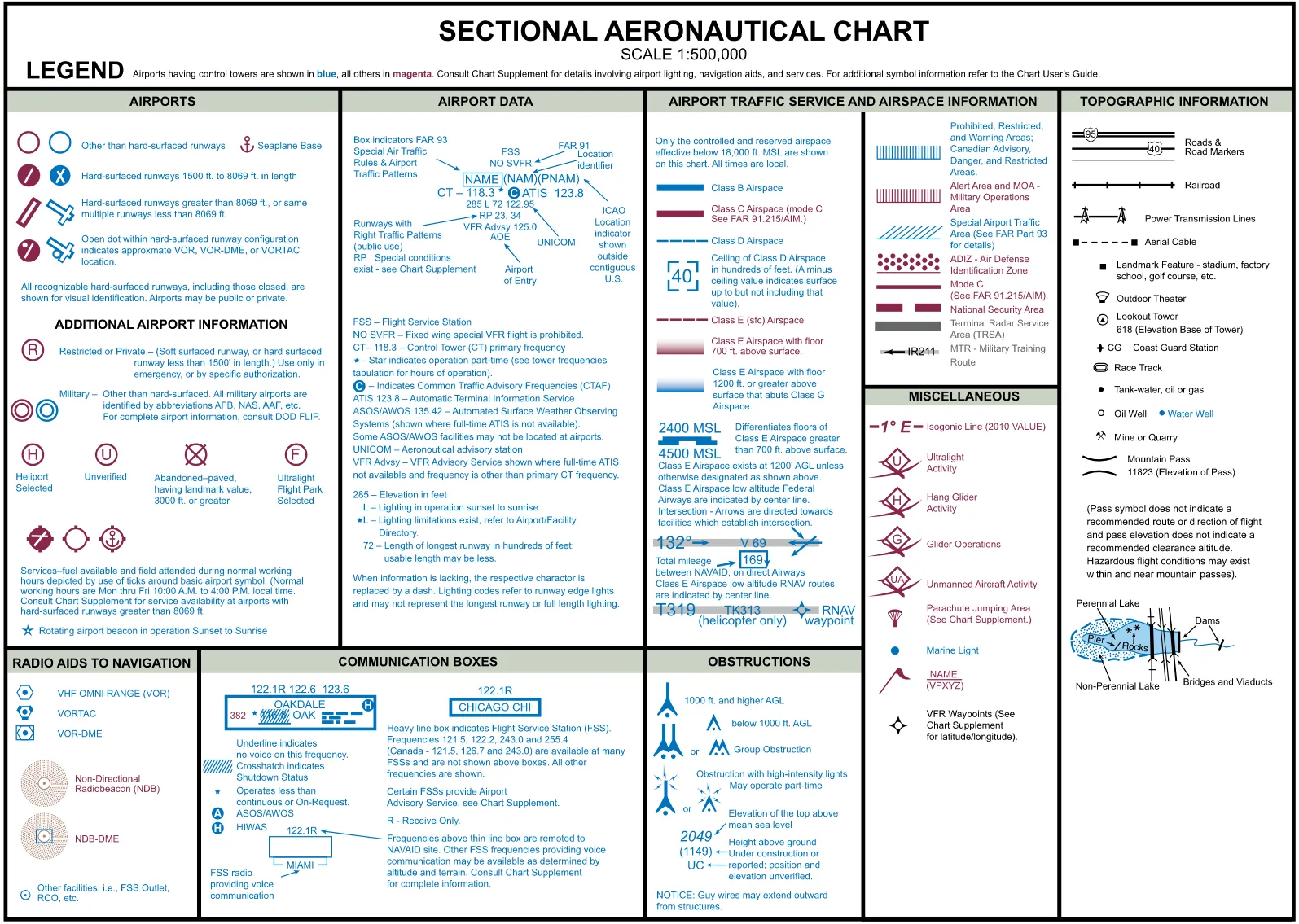
That sentence is: airports having control towers are shown in blue, all others in magenta. Why would a color carry that? Because a tower means a controller is watching the sky around the airport, and that is the single biggest fact about it for anyone who wants to fly nearby. Blue means “someone is in charge here”. Magenta means “this airport has no tower; it may still sit inside airspace you need permission for, and you will have to read the lines to find out”.
The same two inks carry airspace. Class B is a solid blue line and Class C a solid magenta one. Class D is a dashed blue line and Class E surface area a dashed magenta one. The easy way to hold that: B and D are the blue pair, C and E are the magenta pair, and within each pair the busier one is solid and the lesser one dashed. Class B and Class C solid, Class D and Class E dashed.
The legend has eight panels. Airports, Airport Data and Airport Traffic Service and Airspace Information are the three you will use most, so they get their own sections here. Obstructions and Radio Aids to Navigation get one each. Topographic Information holds roads, railroads, power lines, towers and water. Miscellaneous holds the isogonic line and the symbols for activity such as gliders and parachuting. Communication Boxes explains the little frequency boxes next to radio stations.
§ 4.3 — AIRPORT SYMBOLS
Airport symbols
The airport symbol is a circle, and the circle is a small piece of code. It tells you the surface of the runway and how long it is before you have read a single word.
An open circle with no runway inside means the runways are other than hard-surfaced: grass, dirt, gravel or sand. A circle with a runway line drawn through it is a hard-surfaced runway between 1,500 and 8,069 feet long. A runway shape with no circle around it, drawn like the outline of two or more long strips, is either a hard-surfaced runway over 8,069 feet or a field with several hard-surfaced runways under 8,069 feet. Why those two odd numbers? The chart draws runway patterns only at airports with a hard-surfaced runway of at least 1,500 feet, and 8,069 is the same break point the length figure uses (it rounds 8,069 down to 80 and 8,070 up to 81, which comes up in a moment). The point is only that the symbol grows as the airport does.
Aeronautical Chart Users' Guide, VFR Symbology: Airports · Legend 1The runway lines inside the circle are not decoration. They are drawn at the real angle, so a symbol with a slash running northwest to southeast is a runway that points that way. That matters later, when a test question asks which side of runway 13 an airplane is on, because you can see where runway 13 is.
Then come the modifiers. A fuel tick: small marks radiating from the circle mean that fuel is available and the field is attended during normal working hours (the legend defines normal hours as Monday through Friday, 10 a.m. to 4 p.m. local). The Chart Supplement has the details. A star beside the airport means a rotating beacon runs from sunset to sunrise. A circled R is a restricted or private airport, one with a soft-surface or short hard-surface runway, to be used only in an emergency or with specific authorization. A circled H is a heliport. A circled U is an unverified field: a landing area that warrants more than ordinary precaution because current information is lacking or it has peculiar limits. A circled X is an abandoned paved runway, kept on the chart as a landmark when the pavement is at least 3,000 feet. A circled F is an ultralight flight park. An anchor is a seaplane base. A double circle is a military field without hard-surfaced runways. Every military airport, whatever its symbol, carries an abbreviation in its name such as AFB, NAS or AAF, and the legend sends you to a military publication (DOD FLIP) for the full picture.
Private airports are further marked with “(Pvt)” after the name. Private does not mean closed or unimportant. It means the field is not for general public use, but there is still a runway there, and the chart includes it for its landmark value. A low-flying aircraft needs to know it is there, and so do you.
The takeaway is that a symbol plus its color plus the text block beside it is the unit of information. Never judge an airport by its circle alone. (You may also see the word OBJECTIONABLE beside a field. The FAA uses it when an airport’s traffic pattern conflicts with another’s or an obstacle sits close to its runway.)
§ 4.4 — THE AIRPORT DATA BLOCK
The airport data block
Beside each public airport is a small block of text. It looks like noise until you know its grammar, and then it is a one-glance summary. The grammar is fixed, so once you have read one block you can read all of them.
The first line is the airport’s name, with its FAA identifier in parentheses. A box drawn around the name means special air traffic rules apply under 14 CFR Part 93. “NO SVFR” printed above the name means fixed-wing special VFR flight is prohibited there. Outside the contiguous states you may see an ICAO identifier as well, in a second set of parentheses.
Next come the frequencies. If the airport has a control tower, the line starts with “CT” and the tower’s primary frequency. A star after that frequency means the tower works part-time, and the hours are tabulated in the margin of the chart. A circled C marks the CTAF, the Common Traffic Advisory Frequency. At a field with a part-time tower, the CTAF is what you fall back on when the tower is closed, which is the situation the Grand Canyon sample question asks about. “ATIS” is the recorded weather and airport-information broadcast. “ASOS” or “AWOS” is an automated weather station, shown when there is no full-time ATIS. “UNICOM” marks an aeronautical advisory station. “VFR Advsy” is a VFR advisory service, shown when there is no ATIS and the frequency differs from the tower’s. “AOE” means airport of entry. “FSS” means a flight service station is on the field.
Last, the numbers. The first number is the field elevation in feet above sea level. The letter after it is the lighting: L means the runway lights are on from sunset to sunrise; a star before the L, which we write *L here, means there are limits and you must consult the Chart Supplement, for instance lights that the pilot switches on by radio. A dash means no lights. Then the length of the longest runway, in hundreds of feet, rounded using 70 as the break point: a runway 8,069 feet long is charted as 80, one 8,070 feet long as 81. The usable length may be less. Finally “RP” followed by runway numbers means right-hand traffic patterns on those runways, and an asterisk before the RP sends you to the Supplement for special restrictions. When any piece of information is lacking, a dash takes its place so the layout never shifts.
Why CTAF is on the chart at all
An airport without a tower still has traffic, and the pilots in it need a way to avoid hitting each other. The answer is a shared radio frequency on which everyone announces what they are doing: “Town and Country traffic, Cessna 123 is ten miles south, inbound”. The CTAF is that frequency. It may be a UNICOM, a MULTICOM, a flight service frequency or the tower’s own. Most non-towered airports use UNICOM, which is usually 122.8. An airport with no tower, no flight service station and no UNICOM uses the MULTICOM frequency, 122.9.
A remote pilot is not required to talk to manned aircraft, and the study guide says that you should not transmit over an active aviation frequency unless there is an emergency. But listening is how you learn where the traffic is. The CTAF tells you what to tune.
FAA-G-8082-22, Ch. 7| CT 118.3 | Tower frequency; a following star means part-time |
|---|---|
| Circled C | The number beside it is the CTAF |
| ATIS, ASOS, AWOS | Weather broadcast frequencies; not the CTAF |
| First number | Field elevation, feet MSL |
| L, *L, or a dash | Lights sunset to sunrise; lights with limits; none |
| Two digits | Longest runway in hundreds of feet (70 rounds up) |
| RP and numbers | Right-hand traffic on those runways |
§ 4.5 — THE CHART SUPPLEMENT
The Chart Supplement, the chart’s companion
The chart has to fit on a sheet of paper, so it squeezes each airport into a few lines. The Chart Supplement U.S., formerly the Airport/Facility Directory, is where the rest of the information lives. It is a set of books, published in seven regions and revised every 56 days, that gives each public airport, heliport and seaplane base its own entry. The study guide calls it the source that “provides the most comprehensive information on a given airport”, and sample question 11 asks exactly that: for the most comprehensive airport information, the answer is the Chart Supplement, not NOTAMs and not a terminal area chart.
FAA-G-8082-22, Ch. 11 · Chart Supplement U.S., Directory Legend (Legend 2)The best way to see how the chart and the Supplement fit together is to put one airport in both. Coeur d’Alene appears on the chart in Supplement Figure 22 (our FIG. 4-11, read in full in section 4.14), and its directory entry is Supplement Figure 31.
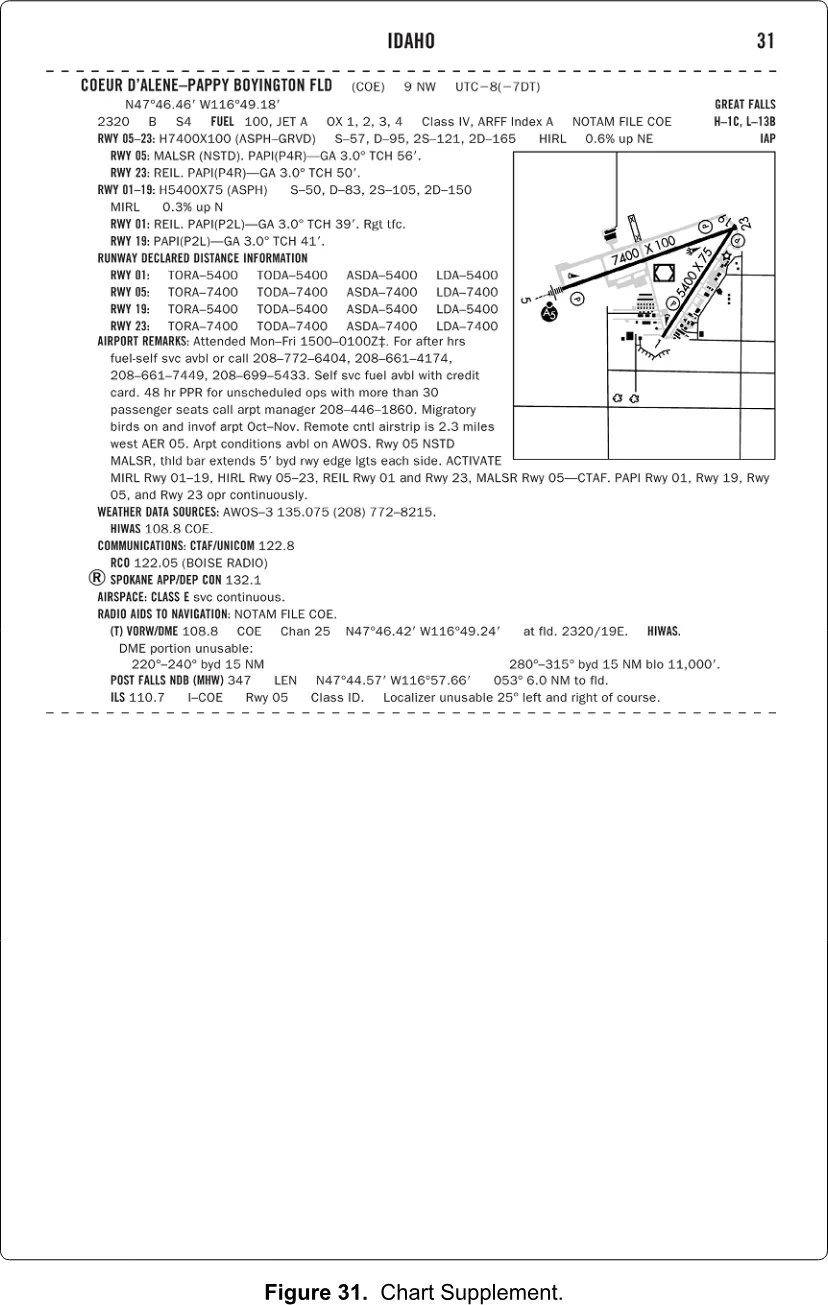
Read the entry from the top. The heading line gives the name, the identifier (COE), the distance and direction from the city (9 nautical miles northwest; Supplement mileages are nautical unless noted), and the time zone as an offset from UTC. Below it come the airport’s coordinates, its elevation (2,320 feet) and services, then each runway with its length and surface: runway 05-23 is 7,400 by 100 feet, runway 01-19 is 5,400 by 75. The remarks say when the field is attended. The weather line gives the AWOS-3 frequency. The communications line says, in plain words, “CTAF/UNICOM 122.8”, which settles which of the three numbers on the chart is the one to monitor. The airspace line says “CLASS E svc continuous”. The radio aids line lists the VOR/DME. The directory legend (Legend 2 in the supplement, a page with thirty-five numbered callouts) decodes every abbreviation.
Two details show why you need both. First, on the chart the airport sits inside a dashed magenta line with the note “See NOTAMs/Directory for Class E (sfc) eff hrs”. The chart tells you that the Class E surface area may not be on all the time, and sends you to the directory for the hours. The directory answers: continuous. Second, times in the Supplement are in UTC, written with a Z. “Attended Mon-Fri 1500-0100Z” is, at a time zone eight hours behind UTC, roughly 7 a.m. to 5 p.m. local.
§ 4.6 — AIRSPACE ON THE CHART
Airspace on the chart
Most of what you need from a sectional is the answer to one question: do I need authorization to fly here? Under 14 CFR § 107.41 you need prior ATC authorization to operate in Class B, Class C or Class D airspace, or within the lateral boundaries of the surface area of Class E airspace designated for an airport. Anywhere else, in Class G or in Class E that begins above where you will be flying, you do not. The chart’s lines and colors are how you tell which is which. The rules and the LAANC system for getting authorization are in the airspace chapter; the lesson on the chart’s airspace rings lets you peel the layers apart one at a time.
14 CFR § 107.41The four lines and their numbers
Class B is a solid blue line. Class B airspace is shaped like an upside-down wedding cake: a surface area in the middle and larger and larger rings above it, so the line you see is really several outlines stacked. Class C is a solid magenta line, with an inner circle that goes to the surface and an outer circle, a shelf, that starts higher up. Class D is a dashed blue line around an airport with a tower. Class E surface area is a dashed magenta line, around an airport with no tower whose airspace is controlled right down to the ground.
On each ring sits a pair of numbers, one above the other, a fraction without the bar. The top number is the ceiling and the bottom number is the floor, both in hundreds of feet above mean sea level, with the last two zeros left off. Class B and Class C figures are printed in the color of the line. So “41 over 13” on a magenta ring means Class C from 1,300 feet MSL to 4,100 feet MSL, and “41 over SFC” means from the surface to 4,100. “SFC” is short for surface. Class D has just one number, in square brackets, because its floor is always the ground: “[40]” is a ceiling of 4,000 feet MSL. A minus sign in front of it, as in “[-25]”, means “surface up to but not including” that altitude, usually because the airspace above takes over at that level.
Why MSL, not AGL? Because airplanes fly by an altimeter set to sea level, and a wedding-cake ring has to mean the same altitude everywhere on the ring, even where the ground rises and falls underneath it. A controller needs one number per layer, and MSL gives it. It is a trap for you, though, because your own ceiling is in feet above the ground. Always convert.
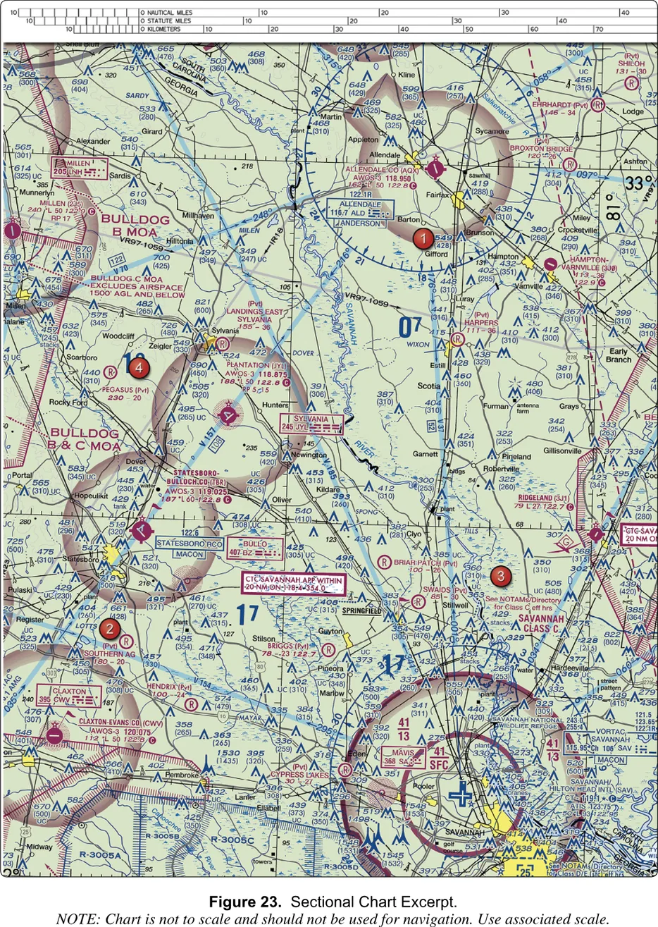
Supplement Figure 23 is the model for this. Savannah, Georgia has a Class C, drawn in magenta around a blue towered airport. Sample question 8, which refers to area 3, asks for the floor of the Class C at the shelf, the outer circle. Look at the ring. The inner circle reads 41 over SFC. The outer shelf, where area 3 sits, reads 41 over 13. The ceiling is 4,100 feet MSL and the floor is 1,300 feet MSL. The answer is “1,300 feet MSL”. One wrong answer is the unit trap (1,300 feet AGL), and another is a number that is not on that ring at all (1,700). The chart never prints AGL in these rings.
Minot International in Supplement Figure 21 is a handy second example. Its Class D carries a bracketed 42. The airport is at 1,716 feet and Class D normally extends 2,500 feet above the airport, which is 4,216 and appears on the chart rounded to 4,200. The chart is describing a real volume of sky, and the arithmetic works out.
FAA-G-8082-22, Ch. 2 · Aeronautical Chart Users' Guide, VFR Terms and SymbolsClass E, and the fade
Class E is the awkward one, because it is nearly everywhere but usually begins far above you. The chart marks where it starts in four ways, and you can learn all four in a minute. A dashed magenta line is Class E that starts at the surface. A magenta fade, a band that shades from a stronger color on one edge to nothing, means Class E that starts at 700 feet above the ground. A blue fade means a floor of 1,200 feet or more above the ground, bordering uncontrolled Class G airspace. And where the floor is some other altitude above 700 feet, the chart prints a symbol and a number, like “2400 MSL”, which means Class E from that altitude up. Class E exists at 1,200 feet above the ground unless the chart says otherwise, and the blue fade is what shows you where that 1,200-foot Class E stops and Class G begins. The chart depicts every Class E base below 14,500 feet MSL, and where it depicts none, Class E starts at 14,500. Class E runs up to, but not including, 18,000 feet MSL, where Class A begins.
For you at a maximum of 400 feet AGL, the consequence is simple and a little surprising. A fade does not matter. Both fades start above your limit, so under a magenta fade you are in Class G, the same airspace you would be in if the page were blank. (The one exception is working beside a tall structure, where § 107.51(b) lets you climb higher.) Only the dashed magenta line, Class E from the surface, means you need authorization. Compare the ring around Cooperstown, North Dakota in Supplement Figure 26 (a fade, no dashes: no authorization) with Jamestown, to its southwest (a dashed magenta line: authorization). Both are small airports with no tower, and the only difference is how the airspace around them is built.
Aeronautical Chart Users' Guide, VFR Terms and Symbols · FAA-G-8082-22, Ch. 2Class G is the leftover. It runs from the ground up to the floor of whatever Class E sits above it, and up to 14,500 feet MSL in the places where nothing else is charted. It is never drawn, because it is the absence of lines. In Class G you need no ATC authorization, but everything else still applies: the 400-foot ceiling, the visibility and cloud rules, and the duty to give way to manned aircraft.
Reading a ring from your own altitude
Because every ring has a floor, a shelf does not necessarily reach the ground. Suppose you want to fly outside the inner circle of a Class C, under its shelf, and the shelf’s floor is 1,300 feet MSL. If the ground where you stand is at 800 feet above sea level, the top of your legal 400 feet AGL is 1,200 feet MSL, below the floor, so you would not be in Class C. If the ground is at 1,000 feet, your top is 1,400 MSL and you would be inside it. The chart gives you the floor in MSL and the terrain in MSL (contour lines and spot elevations), and you do the subtraction. Do it every time, and when the margin is thin, treat the airspace as the controlled class and get the authorization. The rings on a real chart are fiddlier than any example here.
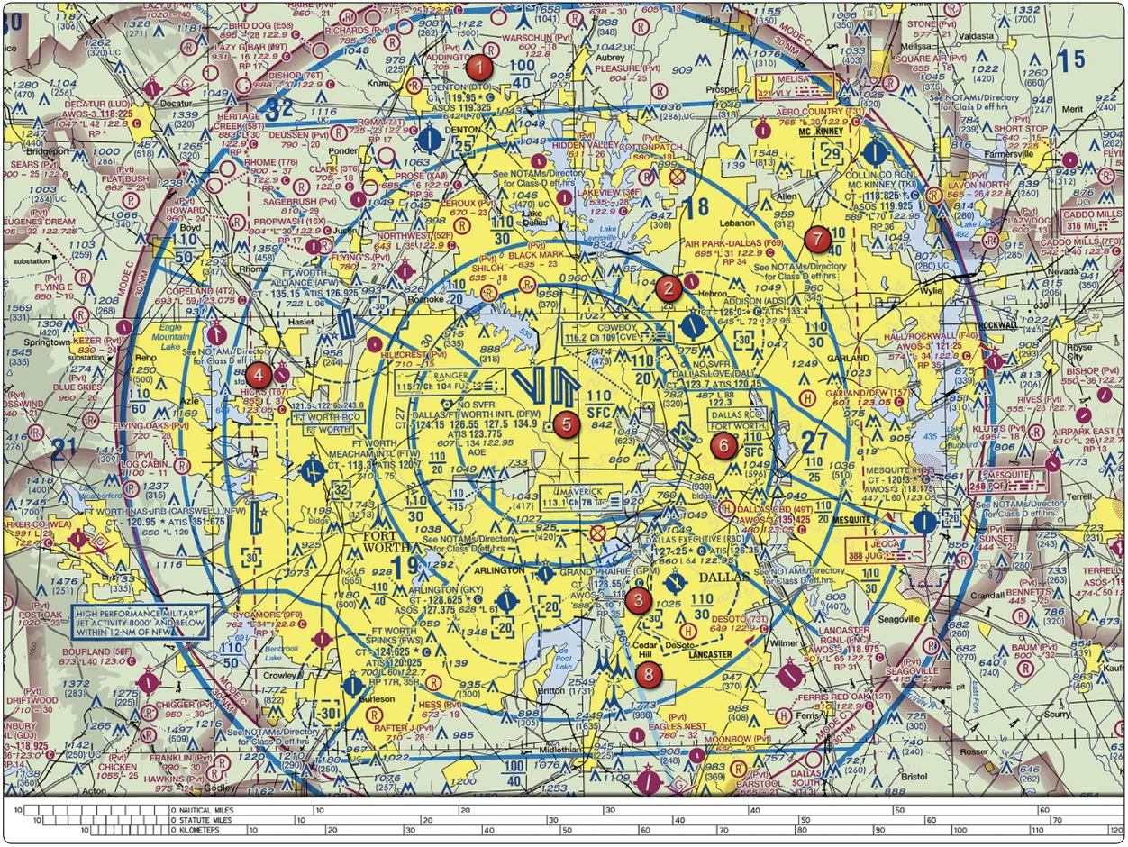
Supplement Figure 25 shows a full Class B. The rings nest like steps, and each ring has its own pair of numbers: 110 over SFC near the middle, then 110 over 20, 110 over 25, 110 over 30 and so on outward. Near the middle the ceiling reads 110, which is 11,000 feet MSL, and the floor under it rises as you move out. At the far edge of the shelves the ceiling itself steps down to 100, or 10,000 feet. That is the upside-down cake. A plus sign before a floor means “from above that altitude”, and the letter T in a ceiling means “up to, but not including, the floor of the airspace above”. Notice also the bracketed numbers in dashed blue, like the [25] by Denton: Class D around a smaller airport. Denton’s block, “CT 119.95” followed by a star, tells you the tower is part-time. And notice the thick magenta ring near the edge of the excerpt, the Mode C veil, which says “MODE C and ADS-B OUT, 30 NM”. Mode C and ADS-B Out are equipment that manned aircraft must carry inside that ring. They are not requirements for you; they are prohibited for you. A small unmanned aircraft system must not operate with a transponder on (14 CFR § 107.52), and ADS-B Out is prohibited too (§ 107.53). The veil is on the chart for the manned world, and you read it as a flag that you are close to a major airport.
14 CFR § 107.52 · 14 CFR § 107.53 · Aeronautical Chart Users' Guide, VFR Terms and SymbolsThe face of Class B on a sectional is dense, but every piece repeats. Find the blue line, read the numbers on the ring you are standing under, convert to AGL, and decide.
§ 4.7 — SPECIAL-USE AND OTHER AIRSPACE
Special-use airspace and everything else on the map
Beyond the alphabet classes, the chart draws areas set aside for special activity. They are drawn with hatching, and the hatching’s color is the tell.
Prohibited, restricted and warning areas are hatched in blue. They carry a letter and a number: P for prohibited (P-40 around Camp David), R for restricted (R-5401), W for warning (W-50A). Alert areas and military operations areas (MOAs) are hatched in magenta. Alert areas carry an A and a number (A-211); MOAs have a name instead of a number (“Devils Lake West MOA”). The type is spelled out inside large areas where there is space.
These areas differ in what they ask of you. A prohibited area is a no-go. A restricted area is airspace with hazards that are often invisible, such as artillery, gunnery or guided missiles, and the rule is that no one may operate a small unmanned aircraft in a prohibited or restricted area without permission from the using or controlling agency (14 CFR § 107.45). A warning area is like a restricted area offshore: it extends from three nautical miles out from the coast, and the purpose is to warn you of danger. An MOA exists to separate military training from instrument traffic, and the thing for you to know is whether it is active, because fast military aircraft are maneuvering inside it. An alert area warns of a high volume of pilot training or an unusual type of aerial activity; everyone inside it remains responsible for collision avoidance. A controlled firing area is not drawn at all.
14 CFR § 107.45 · FAA-G-8082-22, Ch. 2 · Aeronautical Chart Users' Guide, VFR Terms and SymbolsHow do you find out whether an MOA or restricted area is active? The details are tabulated on the chart: altitudes, hours of use and the controlling agency or contact frequency, in blue for prohibited, restricted and warning areas and in magenta for alert areas and MOAs. The study guide adds that the back of the sectional carries the same kind of detail. The Users’ Guide adds an important warning: no NOTAM will be issued to announce times of use that are already published in the tabulation. So the list on the chart is the schedule, and it is the first place to look. For sample question 10, which asks how to find out whether the Devils Lake West MOA is active, that is the idea to hold: the status comes from the chart’s own listing and its controlling agency, not from a drone database.
Other areas, in a paragraph each
Military training routes (MTRs) are drawn as a gray line with an arrow, labeled IR (instrument) or VR (visual) and a number. Fast military aircraft fly them, usually below 10,000 feet MSL at over 250 knots, and the corridor can extend several miles each side of the centerline. The digits tell you how low: a route with no segment above 1,500 feet AGL has a four-digit number (VR1667), and a route with any segment above that has three or fewer digits (IR21). The chart legend shows an arrow and “IR211” as its example.
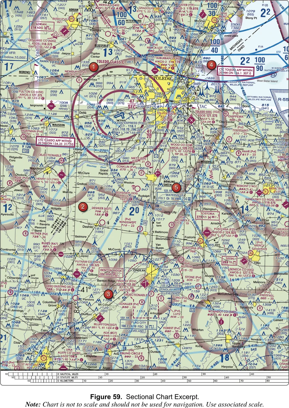
Supplement Figure 59 is the test’s example (sample question 30, area 2). The gray line is labeled with four four-digit VR routes, so they are visual routes with no segment above 1,500 feet AGL. Military aircraft are low and fast there, right where a small drone flies. The answer is “yes, this is a hazard”, and specifically “a military training route from the surface to 1,500 feet AGL”. The wrong answers say that you will be above 400 feet anyway (you will not, because 400 feet is your ceiling) and that the route provides traffic separation for manned aircraft. A route is only a line on which fast military aircraft are expected, and it makes the area more hazardous for you, not safer.
FAA-G-8082-22, Ch. 2 · Aeronautical Chart Users' Guide, VFR Terms and SymbolsActivity symbols. A small magenta symbol with a letter inside marks a miscellaneous activity area: U for ultralight, H for hang glider, G for glider operations, UA for unmanned aircraft activity. A parachute symbol marks a jump area, and the Chart Supplement has the details. These are places where something is usually in the air at low altitude and, in the case of gliders and parachutists, may be hard to see. The legend’s symbols are small; the Users’ Guide says charting a symbol in an area means both miscellaneous activity and regular air operations may be present, and tells pilots to check NOTAMs for more.
Other lines. A Terminal Radar Service Area (TRSA) is a screened black outline with its own altitudes in black. Participation in TRSA service is voluntary. A National Security Area is a broken magenta line with a notice asking pilots to avoid flying through it, and only temporary flight restrictions relating to national security are drawn, as a broken blue line. An Air Defense Identification Zone has its own symbol. A boxed airport name means Part 93 special air traffic rules, and blue diagonal hatching marks the Part 93 area. You do not need to memorize these; you need to know they exist, that they are airspace restrictions, and that the legend explains each.
National parks, wildlife refuges and wilderness. The legend calls these special conservation areas, and the FAA study material lists, alongside them, a request that pilots operate above 2,000 feet above the ground over wildlife areas, wilderness areas and national parks. It is a request, not an airspace class. A small drone is always far below 2,000 feet, so for you the outline is a prompt to find out who manages the land and what they allow, and no chart answers that. On the test it appears as a distractor: sample question 13 offers “Authorization from the National Park Service” and the right answer is something else.
FAA-G-8082-22, Ch. 2 · FAA-H-8083-25, Ch. 15 · Aeronautical Chart Users' Guide, VFR Terms and SymbolsCautions printed right on the chart
Hazards that are not airspace are written onto the chart in boxes. Supplement Figure 20, the Norfolk and Outer Banks excerpt, carries two. One warns of high-density military operations in the vicinity of Oceana Naval Air Station and Fentress Naval Auxiliary Landing Field. The other, south of Elizabeth City Regional, reads “CAUTION: UNMARKED BALLOON ON CABLE TO 3008’ MSL. CHECK NOTAMS.”
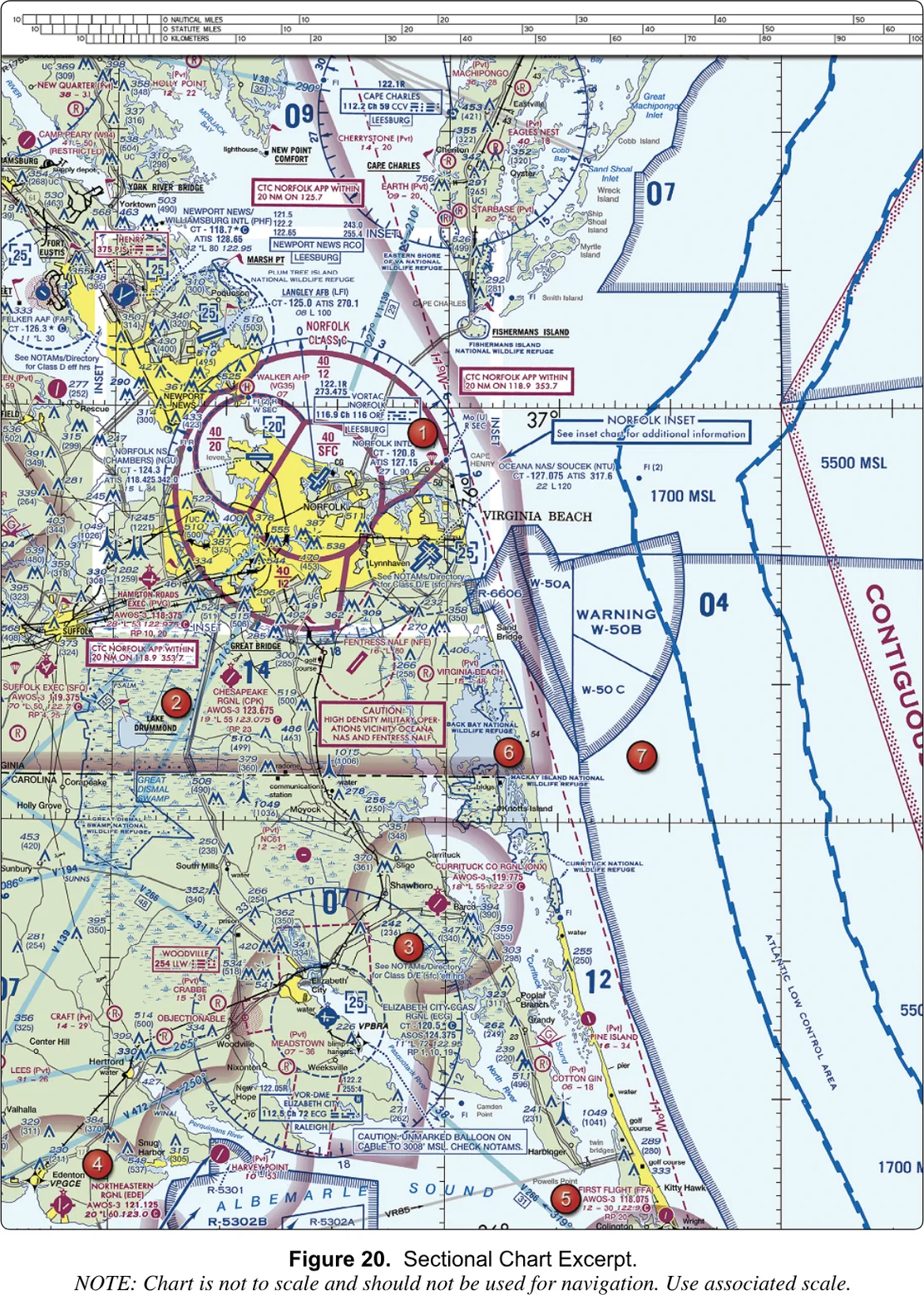
Sample question 9 asks which hazard is indicated southeast of Elizabeth City, and the choices are the military operations, a balloon on a cable to 3,008 feet AGL, and a balloon on a cable to 3,008 feet MSL. The box says MSL, so read what is printed, not what you expect. It is a good habit anyway: a hazard written in MSL on a chart is a hazard whose height above you depends on the ground, so convert before you decide. Sample question 14 asks how a remote pilot checks NOTAMs, “as noted in the CAUTION box”, and the answer is a briefing from an online source such as 1800wxbrief.com. The AC says the remote pilot must check for NOTAMs before each flight, and a caution box that says “check NOTAMs” is the chart reminding you of it.
AC 107-2A, ¶ 2.2 and ¶ 5.10.3§ 4.8 — OBSTRUCTIONS
Obstructions
At 400 feet above the ground, the things most likely to ruin your day are things people built: towers, stacks, wind turbines, power lines. The chart draws them, in blue, as small peaked symbols, and attaches two numbers to the ones it can measure.
The legend gives four sizes. A tall symbol is an obstruction 1,000 feet above the ground or higher. A shorter one is below 1,000 feet. A cluster of two or more is a group obstruction, and in dense places like city centers only the highest obstacle in the cluster is shown, with the group symbol, so that the chart stays readable. Rays flaring out from a symbol mean high-intensity lights, which can run part-time or switch on when something approaches. The legend adds a notice you should take literally: guy wires may extend outward from structures.
The two numbers are the whole trick, and the test loves them. The big one, on top, is the elevation of the very top of the structure above mean sea level. The one in parentheses below it is the height of the structure above the ground. Subtract and you get the elevation of the ground at its foot. In the legend’s example, 2,049 minus 1,149 means the tower stands on ground 900 feet above sea level. When the letters UC appear, the obstacle is under construction, or has been reported and not verified. In very congested areas the parentheses are sometimes left out to avoid clutter.
| Top number | Top of the structure above sea level (MSL) |
|---|---|
| Number in parentheses | Height above the ground (AGL); omitted in crowded areas |
| UC after a number | Under construction, or reported and not verified |
| Charted when over | 200 ft AGL, or 299 ft AGL inside a yellow city tint |
| Tall symbol | 1,000 ft AGL and higher |
| Rays around a symbol | High-intensity lights, possibly part-time |
| Group symbol | Two or more together; only the highest is labeled in dense areas |
Why should a pilot who is capped at 400 feet care about a tower 1,149 feet tall? Three reasons. The first is that the 400-foot limit is measured from the ground, and the ground is not flat. A point 400 feet above the top of a ridge is far higher above sea level than a point 400 feet above the valley beside it, and only the chart’s MSL numbers let you compare them with a tower. The second is the wires. The study guide says guy wires can extend about 1,500 feet horizontally from a structure and are very hard to see in good weather and invisible at dusk, so skeletal structures should be avoided horizontally by at least 2,000 feet. The third is the structure rule itself. Under 14 CFR § 107.51(b), you may fly above 400 feet only within a 400-foot radius of a structure, and no higher than 400 feet above its uppermost point. The “(1149)” on the chart is that structure’s height. A legitimate inspection of that tower could go as high as 1,149 plus 400 feet above the ground, which is 1,549, not a foot more, and only within 400 feet of its sides. The study guide’s 2,000-foot advice is for flying past a tall guyed tower. The § 107.51(b) allowance is for working on one, and it comes with careful planning, because those wires are exactly what you will be close to.
14 CFR § 107.51(b) · FAA-G-8082-22, Ch. 11Power lines get their own symbol, a line with small tower marks joined by wire, and aerial cables a dashed line with a black square at each end. Treat what the chart shows as a minimum, because it cannot draw every wire. “Flying in the wire environment” is on the test’s knowledge list for exactly this reason: the wire you hit is the one nobody drew.
§ 4.9 — TERRAIN AND MEF
Terrain, and the maximum elevation figure
Five tools show the ground on a sectional. Contour lines join points of equal elevation, with basic lines every 500 feet and intermediate lines often every 250. Lines packed together mean steep ground, and lines far apart mean a gentle slope. Shaded relief lights the land from the northwest, because our eyes are used to light from that direction, so the slopes look like hills. Color tints go from light green near sea level through yellow and tan to dark brown at the top, and the chart carries a tint scale at one side (Supplement Figure 22 has a scale running from sea level to 12,799 feet). Obstruction symbols cover what people built. And maximum elevation figures cover what is left.
A maximum elevation figure, or MEF, is a big blue number inside a rectangle formed by the ticked lines the chart draws every 30 minutes of latitude and 30 minutes of longitude. The number is the highest elevation in that rectangle, terrain or obstacle, rounded up to the next hundred feet, with the last two zeros dropped. So a printed “71” means 7,100 feet MSL, and “69” means 6,900. You will see them scattered across every excerpt: 71, 74, 66 and 69 on Supplement Figure 22.
The FAA builds the number to be safe, not exact. For a man-made obstacle, it takes the top elevation, adds 100 feet for possible error in the source map, and rounds up: 2,649 plus 100 is 2,749, charted as 2,800. For a natural feature it also adds 200 feet as an allowance for uncharted trees and structures: a peak at 13,161 plus 100 plus 200 is 13,461, charted as 13,500. The guide warns that the figures are not verified by field surveys. For a remote pilot the use is quick and practical. If you are planning to fly in a rectangle whose MEF is 69, then the highest thing you could meet is 6,900 feet above sea level, and if the ground where you are standing is at 6,400, that margin is not as generous as it looks.
Aeronautical Chart Users' Guide, VFR Terms and Symbols§ 4.10 — LATITUDE AND LONGITUDE
Latitude and longitude
Every point on the Earth has an address made from two angles, and the chart prints the grid so you can use it. This is the part of the chart where the test asks the most mechanical questions. Three of the sample questions use it (13, 24 and 31), and none is difficult once you know the procedure. The interactive latitude and longitude lesson lets you practice the procedure on a live grid.
Latitude lines are the circles drawn parallel to the equator, running east and west. They measure degrees north or south of the equator, from 0 at the equator to 90 at the poles. The lower 48 states lie between about 25° and 49° N. Longitude lines, the meridians, run from the North Pole to the South Pole. They measure degrees east or west of the Prime Meridian, which passes through Greenwich, England, out to 180. The lower 48 lie between about 67° and 125° W. A way to keep them straight: the lines of latitude are the flat rungs of a ladder, and the lines of longitude are the long ones.
Each degree is divided into 60 minutes, not into decimals, exactly as an hour is divided into 60 minutes. A point written 47°40’ N is 47 degrees and 40 minutes north of the equator, two thirds of the way from the 47° line to the 48° line. On the chart, the whole-degree lines are drawn and labeled (you can see “48°” and “101°” in Supplement Figure 21), and each of those lines carries tick marks that you count to get minutes. The Users’ Guide says the chart’s quadrants are the rectangles bounded by ticked lines every 30 minutes.
FAA-H-8083-25, Ch. 16 · FAA-G-8082-22, Ch. 11 · Aeronautical Chart Users' Guide, VFR Terms and SymbolsFinding a point
In the United States, latitude numbers get larger as you go north, and longitude numbers get larger as you go west. That one fact settles the direction of every count. To find 47°40’ N, 101°26’ W you do four things: find the 47° and 48° lines; find the 101° and 102° lines (the 102° line is to the west of the 101° one); count 40 minutes up from the 47° line, or equivalently 20 minutes down from the 48° line; and count 26 minutes west of the 101° line. Where those two counts cross is the point.
The picture is a one-degree square from the chart: 48° N along the top, 47° N along the bottom, 101° W on the right and 102° W on the left. The orange arrows are the two counts, and P is where they meet. In the chart’s Figure 21, the answer to sample question 24 is exactly this: the point falls on Garrison Airport (D05), whose block on the chart reads 1937 *L 37 122.9 and shows the airport’s circle with its runway line. The other two choices are easy to eliminate once you have the rough position, because Semchenko is a private strip a little north and east of Garrison, and Mercer County Regional is near the bottom of the excerpt, about twenty minutes of latitude to the south.
§ 4.11 — SCALE AND DISTANCE
Scale and distance
Every sectional has a scale bar, three rows long, printed along the edge: nautical miles, statute miles and kilometers, one above another. Use the row the question asks for. Test distances are usually statute miles (“approximately 4 SM southeast of Elizabeth City”), and the airspace radii you read in the study guide are nautical. A nautical mile is 6,076.1 feet and a statute mile is 5,280, so a nautical mile is about 1.15 times a statute mile, and a knot (one nautical mile per hour) is 1.15 miles per hour. Divide the 100 mph speed limit by 1.15 and you get 87 knots, which is how § 107.51(a) can state both.
The regulations are a trap here. Your visibility minimum, 3 statute miles, is in statute miles. Class C’s inner circle, five nautical miles, is in nautical. Chart Supplement mileages are nautical unless the entry says otherwise, and its bearings and radials are magnetic. When a number appears with a unit, check it.
To measure, lay the edge of a card on the chart, mark the two points, and slide it down to the scale bar; or count minutes of latitude. The FAA’s candidate bulletin lists scales, straightedges and plotters among the things you may bring into the test room, and the September 2026 advisory says that questions needing a measuring tool will supply one on screen, in a design it has not yet described. Practice both ways, because you will not know which you get.
FAA-H-8083-25, Ch. 16 · 14 CFR § 107.51 · PSI Candidate Information Bulletin, UAG§ 4.12 — VORS AND COMPASS ROSES
VORs and compass roses
A VOR is a ground radio station that tells a manned aircraft its bearing from the station, and the chart marks each one with a blue symbol: a hexagon for a VOR, a hexagon with small tabs for a VORTAC, and a hexagon inside a square for a VOR-DME. Beside it sits a box with the station’s name, its frequency, its channel and its identifier in Morse code. Coeur d’Alene’s reads “VOR-DME, Coeur d’Alene, 108.8, Ch 25, COE”.
Around most VORs the chart draws a compass rose, a ring marked off in degrees and oriented to magnetic north, so a pilot can read a bearing straight off the chart. It is the big circle with a fringe of tick marks that you can see around Jamestown in Supplement Figure 26 and around Coeur d’Alene in Figure 22. In Figure 22 you will also see wide light-blue bands labeled V 120 and V 2. Those are low-altitude federal airways, highways in the sky between VORs, drawn along their centerlines. Dashed magenta lines labeled like “14°30’E” are isogonic lines, which give the local difference between true north and magnetic north.
Why is any of this on a drone test? You are not going to navigate by a VOR. There are three reasons. The test may ask you to name a symbol from the legend. A compass rose looks like an airspace circle and will cost you a question if you mistake one for the other: a rose has degree ticks all the way round, and the airspace lines do not. And magnetic north is the reference for runway numbers: a runway’s number is its magnetic heading in tens of degrees, so runway 13 points about 130 degrees, southeast. You will use that in the worked reading of Supplement Figure 26 below, and the lesson on the traffic pattern and runways covers it in depth.
Aeronautical Chart Users' Guide, VFR Symbology: Radio Aids to Navigation · FAA-H-8083-25, Ch. 16§ 4.13 — THE GROUND ITSELF
Roads, rails, wires, towns and water
The last family of symbols is the ground you can see. Roads are drawn as black lines with route shields for interstates and U.S. highways. Railroads are a line with cross ticks. Power transmission lines, as noted, are towers joined by a line. Small black squares mark landmark features: stadiums, factories, schools, golf courses. Special markers cover lookout towers (with the elevation at the base), outdoor theaters, race tracks, mines and quarries, and oil wells and tanks. Mountain passes get a symbol, with a warning that it does not mean a recommended route and that hazardous flight conditions may exist near them. Water is drawn in two blues: a lighter blue for open water, such as coasts and the Great Lakes, and a darker one for inland lakes and rivers. Dams and bridges have their own marks.
Towns are the yellow patches. A yellow tint marks a populated place, and a small circle stands for one too small to tint. The size and style of the name’s type tells you whether the place has more than 250,000 people, between 25,000 and 250,000, or fewer than 25,000.
None of this is airspace. These are the features a pilot looks out of the window to match against the map, which is called pilotage. They are your reference for answering “where am I” on the chart and for matching a question’s description (“near the town of Jamestown, north of the river”) to a spot. They also hold dangers: the yellow tint raises the minimum charted obstacle height to 299 feet, the power-line symbols are hazards, and lookout towers and stacks are exactly the kind of tall thin thing a drone finds.
Aeronautical Chart Users' Guide, VFR Symbology: Culture, Hydrography · Legend 1§ 4.14 — THREE CHARTS, READ ALOUD
Three charts, read aloud
Now the practice. Each reading below follows the same order, the one a pilot uses without noticing. First find the thing the question names: a place, a coordinate, or an area number. In the supplement, the FAA marks places on the excerpts with numbered red dots, because a question cannot say “the airport near the lake”; the FAA’s two new embedded-image samples name the airport instead. Second, note the color: blue means tower, magenta means none. Third, find the line around it, because that is the airspace. Fourth, read the numbers and check their units. Fifth, look at the margin and the boxes for the note that changes the answer. Each reading ends with what the test asks.
Reading 1: Coeur d’Alene (Supplement Figure 22)
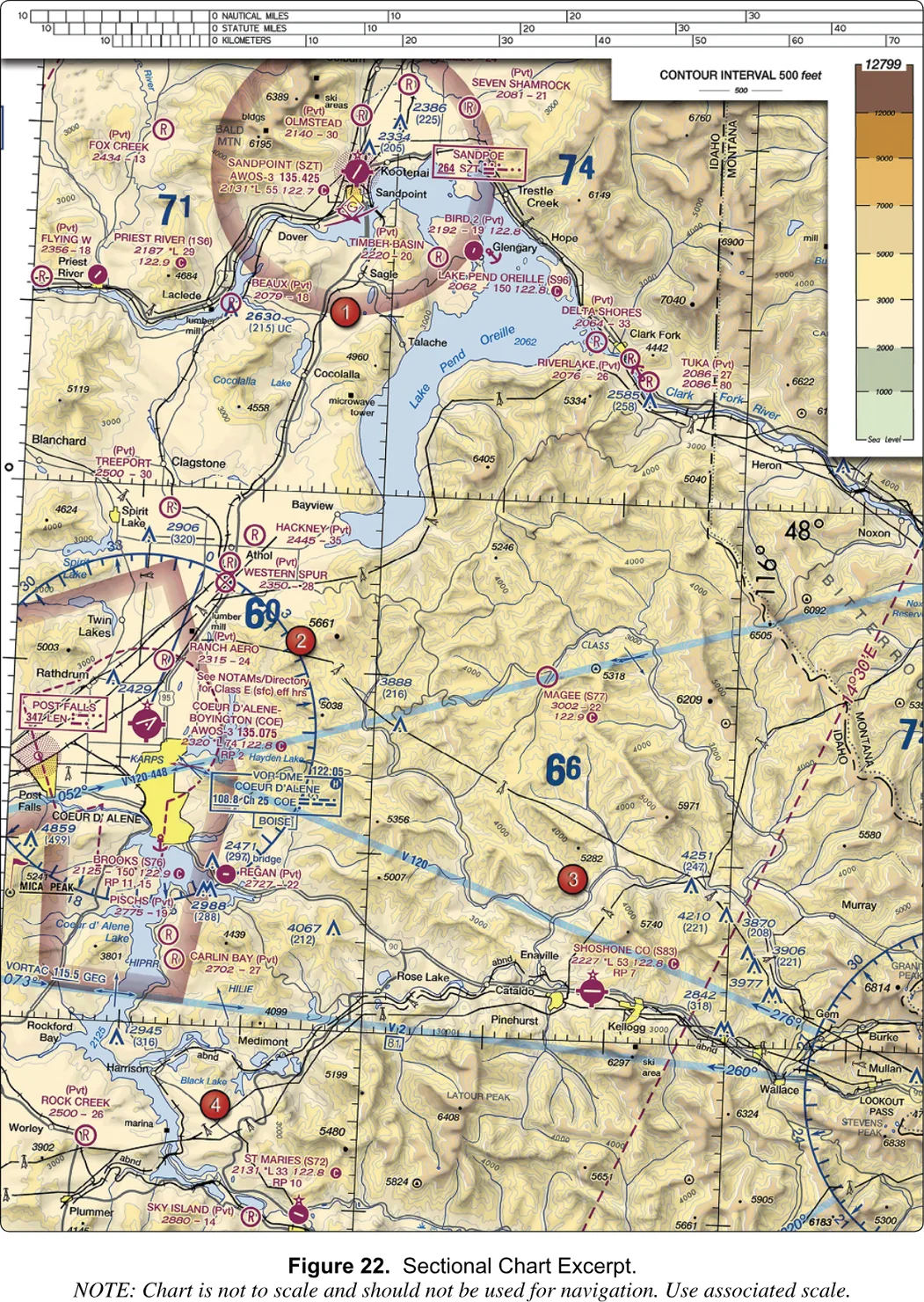
Look at area 2. The red dot sits just above an airport’s data block, northeast of a large magenta airport symbol with crossing runway lines, a little north of the yellow patch that marks the town of Coeur d’Alene.
What do you see? The symbol is magenta, so there is no tower. The crossing runway lines tell you this airport has more than one hard-surfaced runway. To the right of the symbol is the data block you have already taken apart in FIG. 4-2: “COEUR D’ALENE-BOYINGTON (COE)”, an AWOS-3 on 135.075, an elevation of 2,320 feet, a lighting code with a star in front of it, a longest runway of 74 hundred feet, a CTAF of 122.8 with the circled C, and “RP 2”. The Chart Supplement entry in FIG. 4-3 agrees on every point: runway 05-23 is 7,400 feet long, the AWOS is on 135.075 and the CTAF is 122.8. A dashed magenta line surrounds the airport, with the note “See NOTAMs/Directory for Class E (sfc) eff hrs”, so this is a Class E surface area, and the Supplement’s airspace line says that it is in service continuously.
The rest of the clutter explains itself once you know the legend. A blue box just below the airport reads “VOR-DME, COEUR D’ALENE, 108.8, Ch 25, COE”, with the big ring of degree ticks around it that is the VOR’s compass rose, and a small frequency of 122.05 printed above the box. Wide light-blue bands labeled V 120 and V 2 are federal airways. Large blue numbers like 69, 71 and 74 are maximum elevation figures: 6,900, 7,100 and 7,400 feet MSL. The color scale in the corner runs from sea level to 12,799 feet, and the note says the contour interval is 500 feet. The 48° and 116° lines are labeled toward the right side of the excerpt, and a dashed magenta line there, labeled “14°30’E”, is an isogonic line.
What does the test ask? Sample question 5 asks which frequency to use as the CTAF at Coeur d’Alene. The three answers are the three real frequencies you can see near the airport: 122.05 (the radio outlet printed above the VOR box), 135.075 (the AWOS) and 122.8 (the CTAF). Only the last is followed by the circled C, and the Supplement confirms it with “CTAF/UNICOM 122.8”. The answer is 122.8 MHz. Two other questions could be asked of the same spot without changing the figure: whether you need authorization to fly at the airport (yes: it is inside the surface area of Class E airspace designated for an airport, so § 107.41 applies, which is the same logic as the Millville sample), and what the weather frequency is (135.075).
14 CFR § 107.41 · Aeronautical Chart Users' Guide, VFR Symbology: Airports · Chart Supplement U.S., Coeur d'Alene entryReading 2: Jamestown and Cooperstown (Supplement Figure 26)
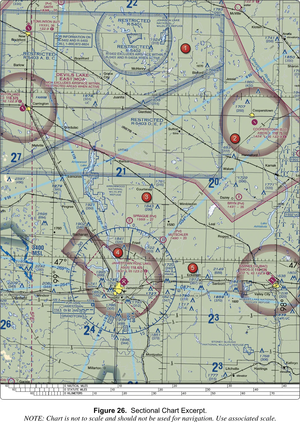
Look at area 1, and take in the whole upper part of the excerpt. The blue hatched outlines are restricted areas: R-5401 is the circle at the top, R-5402 is a larger area whose own note says it excludes the airspace of R-5401 and R-5403A when they are active, and R-5403 is a family of lettered pieces (A, B and C on the west side, D, E and F in the middle). Overlapping them is a magenta hatched Devils Lake East MOA, with its own note that the MOA excludes the airspace within the restricted areas when they are active, and a gray line labeled IR678 with arrowheads is a military training route crossing the whole scene. A boxed note says to call 1-800-972-8824 for information on R-5402 and R-5403. The Users’ Guide says special-use airspace is shown in its entirety even when areas overlap, which is why it looks like a pile.
What does the test ask? Nothing in the sample questions points here, but this is the sort of thing the airspace codes cover. A restricted area has invisible hazards, and under § 107.45 you need permission from the using or controlling agency before you fly in it. The phone number in the box is how you begin. And the MOA’s activity schedule is in the chart’s tabulation, as in Reading 3.
Look at area 2. Cooperstown (S32) is a magenta airport on the east side of the excerpt. The block reads COOPERSTOWN (S32) AWOS-3 118.75 1424 *L 35 122.9, with the circled C. The ring around the airport is a faded magenta band with no dashed line: Class E starting at 700 feet above the ground, so below your 400-foot limit you are in Class G and need no authorization. The runway symbol in the circle is a slash running from northwest to southeast, which is a runway that points toward southeast: runway 13/31. There is no “RP” in the block, so the pattern is the default one: left-hand.
Sample question 18 uses this airport. A pilot on the CTAF reports “midfield left downwind to RWY 13”. Where is the aircraft relative to the runway? Work it out in three moves. The aircraft is landing on runway 13, so it is eventually heading about 130 degrees, southeast. In a left-hand pattern every turn is to the left, so the pattern sits on the left side of the runway as the pilot faces the landing direction: the northeast side. The downwind leg is flown the opposite way (northwest) and parallel to the runway, so the airplane is northeast of the runway, and the nearest of the three offered answers is East. If you were sitting where the aircraft is and looking in its direction of travel, the runway would be on your left. The sectional makes the check easy because the runway is drawn in its true direction.
Look at area 4. Jamestown Regional (JMS) is also magenta, with a block reading JAMESTOWN RGNL (JMS) ASOS 118.425 1500 L 65 123.0 and the circled C. The elevation is 1,500 feet and the longest runway 6,500, and the CTAF is 123.0. Unlike Cooperstown, a dashed magenta line surrounds the airport and runs out toward the southeast: a Class E surface area, so authorization is required inside it. A blue VOR-DME box and its compass rose sit just south. Area 4 itself lies just north of a thin line labeled 47° at the edges of the excerpt.
Two sample questions use this spot. Question 31 asks what the line of latitude at area 4 measures. It is the 47° line, a parallel, and parallels measure degrees north and south of the equator. The other two answers describe longitude, one by naming the Prime Meridian and one by naming Greenwich. Question 13 gives a coordinate, 46.9 N and 98.6 W, and asks what you must receive before flying there to inspect a tower under construction. Convert the decimals: 46.9° N is 46°54’ N, six minutes south of the 47° line; 98.6° W is 98°36’ W, thirty-six minutes west of the 98° line. Count those off the ticks and the point lands just southeast of the airport, within the dashed magenta line (I plotted it by eye from the page image, and the question says “near Jamestown Regional” to tell you the same thing). That is a Class E surface area, so the answer is authorization from ATC. The distractor “Authorization from the National Park Service” refers to nothing on the chart at that spot, and “Authorization from the military” would be right only inside a restricted area, which this point is not.
14 CFR § 107.41 · 14 CFR § 107.45 · FAA-H-8083-25, Ch. 16 · Aeronautical Chart Users' Guide, VFR Terms and SymbolsReading 3: Minot and Garrison (Supplement Figure 21)
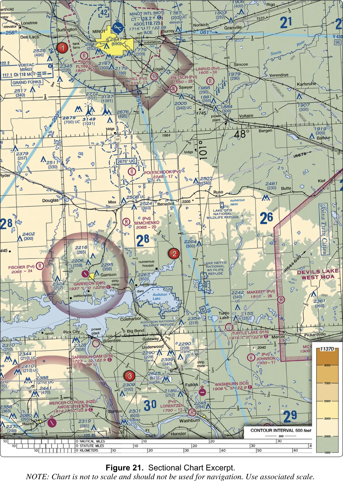
Look at area 2. The red dot is east of Garrison, near the Lake Nettie National Wildlife Refuge. Farther east, a magenta hatched border with the words DEVILS LAKE WEST MOA marks a military operations area, and a gray route, IR644-649, runs along its western edge with an arrowhead.
What do you see? Magenta hatching with a name and no number is a MOA. The chart prints a MOA’s altitudes, hours and controlling agency in its tabulation, and no NOTAM will announce times that are already listed there. Military aircraft train inside a MOA, so you need to know whether it is active before you work in it.
What does the test ask? Sample question 10 sets this scene: you are hired to survey crops inside the Devils Lake West MOA, east of area 2, and you must find out whether the MOA is active. The reading to take from the chart is where the information lives (see the note in section 4.7 about the three options and what the sources do and do not settle). The habit to build is to treat a magenta-hatched name as an invitation to look up its schedule, not as a boundary you can ignore.
Now the coordinate. Sample question 24 asks which airport is at 47°40’ N and 101°26’ W. Use the method from FIG. 4-10. The 48° N line is labeled in the upper right of the excerpt, and the 101° W line is the vertical line labeled just to its left. You want a spot 20 minutes south of the 48° line and 26 minutes west of the 101° line. Go down 20 minutes from the 48° line and west 26 from the 101° line, and you arrive at Garrison Airport (D05), a magenta airport with a ring of faded magenta and the block GARRISON (D05) 1937 *L 37 122.9 with the circled C. Its CTAF is 122.9, the MULTICOM frequency used where an airport has no tower, flight service or UNICOM. The answer is Garrison Airport. Mercer County Regional is about twenty minutes of latitude farther south, and Semchenko is a private strip a little to the north and east.
One more thing is worth seeing here, because it is the Class D example from earlier. At the top, Minot International (MOT) is blue, so it has a tower, and a dashed blue circle surrounds it with a bracketed 42, meaning a ceiling of 4,200 feet MSL.
Aeronautical Chart Users' Guide, VFR Terms and Symbols · 14 CFR § 107.41What the three have in common
None of those questions needed the figure to be memorized. Each one needed a color, a line, a number with its unit, or a count of ticks. That is what the new embedded-image test asks of you too: a different slice of the country, the same grammar. When you meet a chart you have never seen, go back to the five moves: find the thing, note the color, trace the line, read the number with its unit, check the margin. And when you feel unsure about a symbol, the legend is in front of you.
Go back to the airspace chapter for the rules these lines stand for. Then practice the same moves interactively in Reading a sectional, The chart’s airspace rings and Latitude and longitude.
You should now be able to
- Tell a towered airport from a non-towered one by its color, and read a runway symbol for surface and length
- Read an airport data block and pick the CTAF out of three frequencies on the same airport
- Decide from the line around a spot (solid, dashed, fade) whether it needs ATC authorization
- Read an airspace floor or ceiling as MSL and convert it to your own height above the ground
- Read an obstruction label: MSL on top, AGL in parentheses, UC for unverified
- Find a point from its latitude and longitude, and say what a line of latitude measures
- Recognize MOAs, restricted areas and military training routes, and know where their schedules are listed
- Use the Chart Supplement to settle what the chart leaves open