§ 6 — Loading and performance
Loading and performance
Why weight, balance, bank angle and thin air change what your aircraft can do, and the handful of numbers the test asks about.
This is the smallest slice of the test. By the FAA’s current weighting, loading and performance is about 2% of the questions, which works out to roughly one question per sitting. It is also the one chapter that is pure physics, and you will use that physics on every flight you ever make. A drone that hovers at 3 pounds with a camera hovers differently at 3.8 pounds with a camera and a spotlight bolted to the front. Knowing why is what keeps the second flight from ending in a field.
So read this chapter for two reasons. First, to pick up the one point the test almost certainly asks about. Second, because the same ideas, weight, balance, load factor, thin air, cold batteries, are behind a large share of real small-UAS accidents.
§ 6.1 — THE FOUR FORCES
Four forces, two kinds of aircraft
Every aircraft that has ever flown is being pushed around by the same four forces. Weight pulls it down toward the center of the Earth. Lift pushes it up. Thrust pushes it forward, or in a multirotor’s case mostly up. Drag pushes back against whatever motion it has through the air.
FAA-G-8082-22, Ch. 4The relationship between weight and lift is the one to hold onto. In steady level flight, lift equals weight and the aircraft neither climbs nor descends. If lift drops below weight, the aircraft sinks; if lift exceeds weight, it climbs. Everything else in this chapter is a consequence of that balance being disturbed, by extra weight, by a turn, by thin air, or by a battery that cannot deliver the power it used to.
FAA-G-8082-22, Ch. 4A fixed-wing UA and a multirotor satisfy that balance in completely different ways, and the difference explains most of what follows.
A fixed-wing aircraft gets lift from its wings. Air has to flow over them fast enough to generate lift, which means the aircraft must keep moving forward. The propeller supplies thrust to overcome drag and hold that speed. Take away the speed and the wing stops lifting: that is a stall, covered below. The aircraft’s weight acts at its center of gravity, the lift acts through a point on the wing called the center of pressure, and the designer arranges those two points so the aircraft naturally wants to fly straight and level.
FAA-G-8082-22, Ch. 4A multirotor has no wing doing the lifting. Its propellers are the wings. They spin, and the thrust they make is the lift. In a hover, the total thrust from all the rotors exactly equals the weight, and nothing else is needed. That is why a multirotor can hang in the air with no forward speed, and also why it has nowhere to go if the motors cannot make enough thrust. A fixed-wing aircraft that loses power can glide; a multirotor that loses thrust simply falls.
To move sideways, a multirotor tilts. Tilting points part of the thrust horizontally, which pushes the aircraft that way; the vertical part of the thrust shrinks, so the rotors have to work harder to keep the vertical part equal to weight. That small extra effort is a first hint of the theme running through this chapter: a multirotor is always doing arithmetic with its motors, and every extra pound or tilted degree eats into the margin it has left.
§ 6.2 — WEIGHT AND BALANCE
Weight and balance, in principle
Two questions decide whether an aircraft is loaded safely. How much does it weigh, and where does that weight sit? The first is an issue of totals and limits. The second is balance, and it is subtler.
The FAA says it plainly: compliance with the weight and balance limits of any aircraft is critical to flight safety. Operating above the maximum weight compromises the structure and hurts performance. Operating with the center of gravity outside its approved limits results in control difficulty.
FAA-H-8083-25C, Ch. 10For a small UA the legal ceiling is easy to remember. A small unmanned aircraft is one that weighs less than 55 pounds on takeoff, including everything on board or attached to it. So the 55-pound figure is a total that includes payload, battery and any gadget you clipped on.
14 CFR § 107.3Most aircraft you fly will have a manufacturer’s maximum takeoff weight far below that, and that manufacturer’s number is the one to respect.
The vocabulary
The weight-and-balance world has its own small vocabulary. You do not need it for a drone’s day-to-day flying, because a consumer multirotor comes pre-balanced from the factory, but the test uses these words and the logic is worth having.
| Datum | The imaginary vertical line all measurements start from. The manufacturer picks it. | FAA-H-8083-25C, Ch. 10 |
|---|---|---|
| Arm | Distance from the datum to an item, in inches. Plus if aft of the datum, minus if forward. | FAA-H-8083-25C, Ch. 10 |
| Moment | Weight times arm. The twisting effect of that weight about the datum, in inch-pounds. | FAA-H-8083-25C, Ch. 10 |
| Center of gravity (CG) | The point where the whole aircraft would balance if you suspended it there. | FAA-H-8083-25C, Ch. 10 |
| CG limits | The forward and aft points the CG must stay between. | FAA-H-8083-25C, Ch. 10 |
| CG range | The distance between the forward and aft limits. | FAA-H-8083-25C, Ch. 10 |
The idea is the same one as a playground seesaw. A heavy child sitting close to the pivot can balance a light child sitting far from it. What matters is not just the weight but the weight multiplied by the distance from the pivot. That product, weight times arm, is the moment. To balance, the moments on both sides of the pivot have to match.
FAA-H-8083-25C, Ch. 10The FAA’s own illustration uses a board. Put a 50-pound weight 100 inches from the datum and you have a moment of 5,000 inch-pounds. To balance that, any combination that multiplies to 5,000 on the other side works: a 100-pound weight 25 inches out and a 50-pound weight 50 inches out add up to 2,500 plus 2,500.
FAA-H-8083-25C, Ch. 10The one formula
To find where a loaded aircraft actually balances, add up all the weights, add up all the moments, and divide.
FAA-H-8083-25C, Ch. 10Here is a worked example for a small fixed-wing UA with a datum at the nose. The numbers are made up for teaching; they are not from any real aircraft, but the method is exactly the FAA’s.
| Airframe, motor, electronics | 14.0 lb × 20 in = 280 in-lb |
|---|---|
| Battery | 4.0 lb × 14 in = 56 in-lb |
| Camera payload | 2.0 lb × 10 in = 20 in-lb |
| Totals | 20.0 lb and 356 in-lb |
| CG | 356 ÷ 20.0 = 17.8 in aft of the datum |
| Allowed CG range | 16.5 to 19.0 in, so this loading is in limits |
One caution before moving on: the CG is not a point marked on the aircraft. It is wherever the weight happens to be concentrated, and it moves when you load things differently or when something is used up.
FAA-G-8082-22, Ch. 4The test will not ask you to carry out a calculation like this one for a small UA. But the logic it teaches shows up in the questions you will see: what happens to balance if the payload moves, and who tells you the answer.
What happens when you move something
You can also run the formula in reverse to see what a shift does. If you move a weight toward the tail, you add moment; if you move it toward the nose, you remove moment. The total weight does not change, but the CG does.
FAA-H-8083-25C, Ch. 10Take the example above and add a 1.5-pound second payload on a boom, 36 inches behind the nose. Total weight becomes 21.5 pounds and total moment becomes 356 plus 54, which is 410 inch-pounds. Divide: the CG is now 19.07 inches. That is just past the 19.0-inch aft limit. Nothing about the aircraft looks different, and it would probably still take off, which is exactly why this is dangerous.
Now fix it the way a pilot would, by moving weight rather than removing it. Slide the 4-pound battery forward from 14 inches to 8 inches. You remove 4 times 6, which is 24 inch-pounds, leaving 386. Divide by 21.5 and the CG is 17.95 inches, safely inside the range again. The FAA’s rule of thumb for this is a proportion: the weight moved, divided by the total weight, equals the CG change divided by the distance it was moved. Four pounds over 21.5 pounds, times 6 inches, is 1.12 inches, which is the shift you just saw.
FAA-H-8083-25C, Ch. 10§ 6.3 — CENTER OF GRAVITY
CG limits, and what a wrong CG does
The manufacturer sets two limits, a forward limit and an aft limit, and the CG must stay between them for the whole flight. If it is not within the allowed limits after loading, the fix is to move or remove something before takeoff.
FAA-H-8083-25C, Ch. 10Why are there limits at all? Stability and control. Stability is the aircraft’s tendency to correct for a disturbance and return to its original flight path. Controllability is how well it answers the pilot’s inputs. Loading changes both.
FAA-G-8082-22, Ch. 4Fixed-wing: too far forward, too far aft
Think of a dart. A dart is weighted at the front, and that weight keeps it pointed forward. A fixed-wing aircraft is the same: the designer puts the CG slightly ahead of the center of lift so the aircraft has a gentle nose-down tendency and naturally resists tumbling.
FAA-H-8083-25C, Ch. 10Move the CG too far forward and the aircraft becomes nose-heavy. It takes more control authority to raise the nose, especially at the slow speeds of takeoff and landing. Stall speed rises, and control forces rise. In extreme cases the pilot cannot flare to land at all.
FAA-H-8083-25C, Ch. 10Move it too far aft and the problems are subtler and worse. The aircraft becomes less stable: it is less able to right itself after a gust or a maneuver. Control forces become very light, which sounds nice and is not: it makes it easy to overstress the aircraft without feeling it. Stalls can become violent, and recovery from them gets harder.
FAA-H-8083-25C, Ch. 10The two limits are not symmetrical in what they protect. The forward limit is set largely by landing: whether the controls have enough authority to bring the nose up. The aft limit is set by stability: how far back the CG can go before the aircraft stops wanting to fly straight. That is why an aft CG is generally the more dangerous mistake.
Multirotor: it is about the motors
A multirotor has no wing and no tail, so the words nose-heavy and tail-heavy mean something different. The flight controller keeps the aircraft level by making the motors on one side spin a little faster or slower than the motors on the other. When the CG sits exactly in the middle of the motors, they all carry an equal share and need only tiny corrections.
When the CG is offset, say because you mounted a heavy camera on one end, the motors closest to the weight have to push harder to hold that side up, and the motors on the opposite side coast. Three things go wrong at once.
First, the heavily loaded motors may run out of headroom. They are already near full throttle just to hold the aircraft level, so when a gust or a stick input asks them for more, there is nothing left to give. That is called motor saturation, and the result is that the aircraft cannot correct a tilt in the direction it needs to.
Second, you lose control authority. The flight controller steers by making small differences between motors. If some motors are already near the top or the bottom of their range, there is little room for differences, so the aircraft feels sluggish or drifts.
Third, flight time drops. Motors working harder draw more current. An unbalanced aircraft runs a higher average throttle than a balanced one, so the same battery lasts less time. This is an engineering consequence of how multirotors work, not a number from an FAA publication, but it is the reason a lopsided payload often shows up first as a battery that runs down faster than the app promised.
§ 6.4 — PAYLOAD
Payload placement and the manufacturer’s instructions
When you put something on a small UA, you change two things at once: the total weight and the location of the CG. A sensor on the belly shifts the CG down. A light on the front shifts it forward. A parachute on top shifts it up. A spreader tank slung under the center changes its weight as it empties. The FAA’s study guide describes it as a variable load: as items are shifted or expended, the CG shifts with them, and the remote pilot should work out how.
FAA-G-8082-22, Ch. 4The regulation addresses this directly. Before flight the remote pilot in command must make sure that any object attached or carried by the aircraft is secure and does not adversely affect the flight characteristics or controllability.
14 CFR § 107.49(e)This is a short rule with two halves. Secure means it will not shift, fall off or come loose in vibration, a turn or a gust. Does not adversely affect the flight characteristics or controllability means that the aircraft, with the payload on, still flies the way the manufacturer intended it to.
There are two practical consequences. First, you cannot know whether a payload affects controllability without some information about the aircraft’s limits, and that information comes from the manufacturer. Second, loading is not something to improvise. Where the instructions specify a mounting location, a maximum payload weight or an approved accessory, you use it.
FAA UAG sample questions, Q28The FAA’s advisory circular makes the same point from the manufacturer’s side. It lists the information it encourages manufacturers to provide to remote pilots: maximum weights, weight and balance information, operating temperature limits, power source endurance and consumption, and altitude and weather limitations. If you have a flight manual for your aircraft, those are the numbers that matter.
AC 107-2A, ¶ 8.12.2.5For operations over people, the stakes go up. An aircraft eligible for Category 2 or Category 3 may carry only the camera and payloads the manufacturer lists, and an unlisted payload makes the aircraft ineligible for those categories.
AC 107-2A, ¶ 8.12.2.2§ 6.5 — LOAD FACTOR
Load factor: why a turn makes the aircraft heavier
Here is the idea behind the one question you are most likely to see. In a banked turn, a fixed-wing aircraft’s wing has to do more than hold the aircraft up. It also has to bend the flight path. The wing therefore has to produce more lift than the aircraft weighs, and the structure feels that extra force.
The measure of this is the load factor: the ratio of the lift the wing is producing to the aircraft’s weight, expressed in G. A load factor of 1 means the wing is carrying exactly the aircraft’s weight, as in level flight. A load factor of 3 means the structure is feeling three times the weight. Any force that deflects the flight path from a straight line produces this stress.
FAA-G-8082-22, Ch. 4Why does banking do it? Because when the wing tilts, its lift tilts with it. Some of the lift now points sideways, which is what turns the aircraft, and only the vertical part is left to hold the aircraft up. To keep altitude, the wing must produce enough total lift that the vertical part still equals weight. The steeper the bank, the larger that total must be.
The numbers have a clean source. For a coordinated, level turn, the load factor is 1 divided by the cosine of the bank angle. At 30 degrees the cosine is about 0.866, so the load factor is about 1.154. That is not a number to calculate on test day, because the FAA hands you the table.
| Bank 0° | 1.000 G | Figure 2 |
|---|---|---|
| Bank 10° | 1.015 G | Figure 2 |
| Bank 30° | 1.154 G | Figure 2 |
| Bank 45° | 1.414 G | Figure 2 |
| Bank 60° | 2.000 G | Figure 2 |
| Bank 70° | 2.923 G | Figure 2 |
| Bank 80° | 5.747 G | Figure 2 |
| Bank 85° | 11.473 G | Figure 2 |
| Bank 90° | Not possible at constant altitude | Figure 2 |
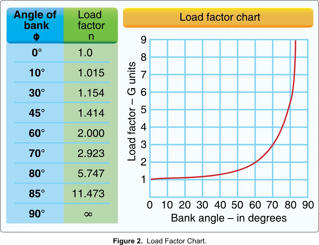
Look at the shape of it. From level flight to 30 degrees the load factor only grows by about 15%. Between 30 and 60 degrees it nearly doubles. After 60 it explodes. The FAA’s own prose says the load factor climbs at a terrific rate after the bank passes 45 or 50 degrees, and that a 90-degree banked turn at constant altitude is mathematically impossible.
FAA-G-8082-22, Ch. 4How the test asks it
The sample question gives a 33-pound unmanned airplane and asks what weight its structure must support in a 30-degree banked turn while holding altitude. Open Figure 2, read across from 30 degrees, and find 1.154. Then multiply: 33 times 1.154 is 38.08 pounds, so the answer is about 38 pounds. The other options, 34 and 47, are tempting because 34 is roughly 33 plus a little and 47 is roughly 33 times 1.414, the 45-degree row. The mistake the question is built to catch is reading the wrong row.
FAA UAG sample questions, Q7 · FAA-CT-8080-2H, Figure 2 FAA UAG sample questions, Q20Two things follow for a real pilot. The first is about structure: any force that bends the flight path, whether a steep turn, a sharp pull-up or a gust, loads the aircraft beyond its resting weight, and a structure designed to carry a certain amount of overload will eventually be asked for more than it can give. The second is about stalling, which brings us to the next section.
A word on multirotors. A multirotor flies a turn differently. It tilts to accelerate sideways and does not rely on wing lift, so the table does not describe its stability in the same way. The test, though, asks the load-factor question about airplanes, and the table applies as printed. Know the table; do not worry about extending it to a quadcopter.
§ 6.6 — STALLS
Stalls and the critical angle of attack
A wing makes lift by deflecting air. The angle between the wing and the oncoming air is the angle of attack. Increase it and the wing makes more lift, up to a point. Beyond a particular angle, the smooth flow of air over the top surface breaks away from the wing. Lift collapses and drag climbs. That is a stall.
FAA-G-8082-22, Ch. 4The point is that a stall has nothing to do with the engine or the speed in the way people expect. A stall happens when the wing exceeds its critical angle of attack. Speed matters only because, at a given weight, slower flight needs a higher angle to make enough lift. But an aircraft can be stalled at any airspeed if the angle is high enough.
FAA UAG sample questions, Q21Load factor connects to this. When you pull more G, the wing needs more lift, which means a higher angle of attack, which means you reach the critical angle sooner. The result is that stalling speed rises with the square root of the load factor.
FAA-G-8082-22, Ch. 4The FAA gives two examples. An aircraft that stalls at 50 knots in straight flight stalls at 100 knots at 4 G. In a turn steep enough to produce 3 G, an aircraft with a 45-knot stall speed must be kept above roughly 75 knots to avoid stalling, the arithmetic is 45 times the square root of 3, about 78 knots, and the Study Guide states it as greater than 75.
FAA-G-8082-22, Ch. 4A small fixed-wing UA flying a tight, fast turn at low altitude is precisely where this bites: the turn feels like normal flying, the extra load factor is invisible, and the wing is closer to its stall than the airspeed readout suggests. Stalls near the ground cannot be recovered.
Multirotors do not stall in this wing sense, so none of this applies to a quadcopter. They have their own cliff edge: they fall off the thrust margin discussed above.
§ 6.7 — WEIGHT AND PERFORMANCE
What weight does to performance
Performance is the word for what an aircraft can actually do: climb, hold altitude, stay up, go far, maneuver. The FAA’s list of what extra weight does is blunt. An overloaded aircraft has a higher takeoff speed, a longer takeoff run, a reduced rate and angle of climb, a lower maximum altitude, a shorter range, a reduced cruising speed, reduced maneuverability, a higher stalling speed, a higher landing speed and a longer landing roll.
FAA-G-8082-22, Ch. 4 · FAA-H-8083-25C, Ch. 10Not every item applies to every aircraft, since a multirotor has no takeoff run. Translate the list. For a small UA, extra weight means climbing slower, less top altitude, less endurance, less margin for gusts and slower response to the sticks. The first sign of a badly loaded aircraft is usually at takeoff, because that is where the aircraft needs the most from its motors in the shortest time.
FAA-H-8083-25C, Ch. 10Why is weight so punishing? For a fixed-wing, extra weight means the wing must fly at a higher angle of attack to hold altitude and speed. That raises drag, and extra drag means extra thrust is needed, which leaves less reserve thrust for climbing.
FAA-G-8082-22, Ch. 3bFor a multirotor the chain is shorter. Extra weight means the motors must spin faster to hover. Faster motors draw more current, and a battery that holds a fixed amount of energy runs down sooner. Energy used is power times time, so heavier means more power, which means less time. It is worth knowing that the relationship is not forgiving: a payload that adds a fifth to the weight usually costs more than a fifth of the flight time, because the motors are working harder on top of working longer.
That last sentence is engineering reasoning, not an FAA statement, and your own aircraft’s manual is the place to find the real numbers for your machine. The principle to carry is the one the FAA states: excessive weight reduces safety margins, and it becomes much more hazardous when other performance-reducing factors, such as heat or altitude, pile on top.
FAA-H-8083-25C, Ch. 10Weight also changes during the flight. For a fuel-powered aircraft, burning fuel makes it lighter and improves performance, though it can disturb the balance. The FAA notes that on small UA, weight can change in flight when expendable items are used, such as a jettisonable load. A battery does not get lighter as it drains, so an electric aircraft does not get this benefit. It simply gets weaker.
FAA-G-8082-22, Ch. 4§ 6.8 — DENSITY ALTITUDE
Thin air: density altitude
Both lift and thrust depend on there being air to push against. An aircraft does not know what altitude it is at in feet; it only knows how dense the air is. Density altitude is the way pilots talk about that. It is the altitude in the standard atmosphere that has the same air density you are actually in. Whatever your actual elevation, the aircraft performs as though it were operating at the density altitude.
FAA-H-8083-25C, Ch. 11So high density altitude means thin air and worse performance; low density altitude means thick air and better performance. Three things push the density altitude up: high elevation, high temperature and high humidity. Low pressure does too. Cool, dry air at low elevation is the opposite and gives the best performance.
FAA-H-8083-25C, Ch. 11Humidity surprises people. Water vapor is lighter than the nitrogen and oxygen it displaces, so moist air is less dense than dry air. A hot, humid afternoon is a worse day for your aircraft than a hot, dry one. There is no simple chart for the humidity effect, but the FAA says to expect a decrease in overall performance in high humidity.
FAA-H-8083-25C, Ch. 11The FAA’s own example is worth remembering. A pressure altitude of 5,000 feet at standard temperature would need a ground run of about 790 feet. With the temperature 20 degrees Celsius above standard, the density altitude is above 7,000 feet, and the ground run grows to nearer 1,000 feet. The temperature was not extreme; it simply moved the air density up two thousand feet.
FAA-H-8083-25C, Ch. 11For a small UA, thin air hurts twice. The wing of a fixed-wing needs a higher speed to make the same lift, and the propellers of either type bite less air with every turn, so thrust drops. A multirotor in thin air spins its motors faster to hold a hover, draws more current and has less throttle left in reserve. This is why a drone that flies beautifully at the coast can feel mushy at a mountain site in July.
Reading the chart
The test supplement includes a density altitude chart, Figure 8. It has two parts. The chart itself plots outside air temperature along the bottom and approximate density altitude up the side, with slanted lines for each pressure altitude. The table beside it converts an altimeter setting into a pressure altitude correction.
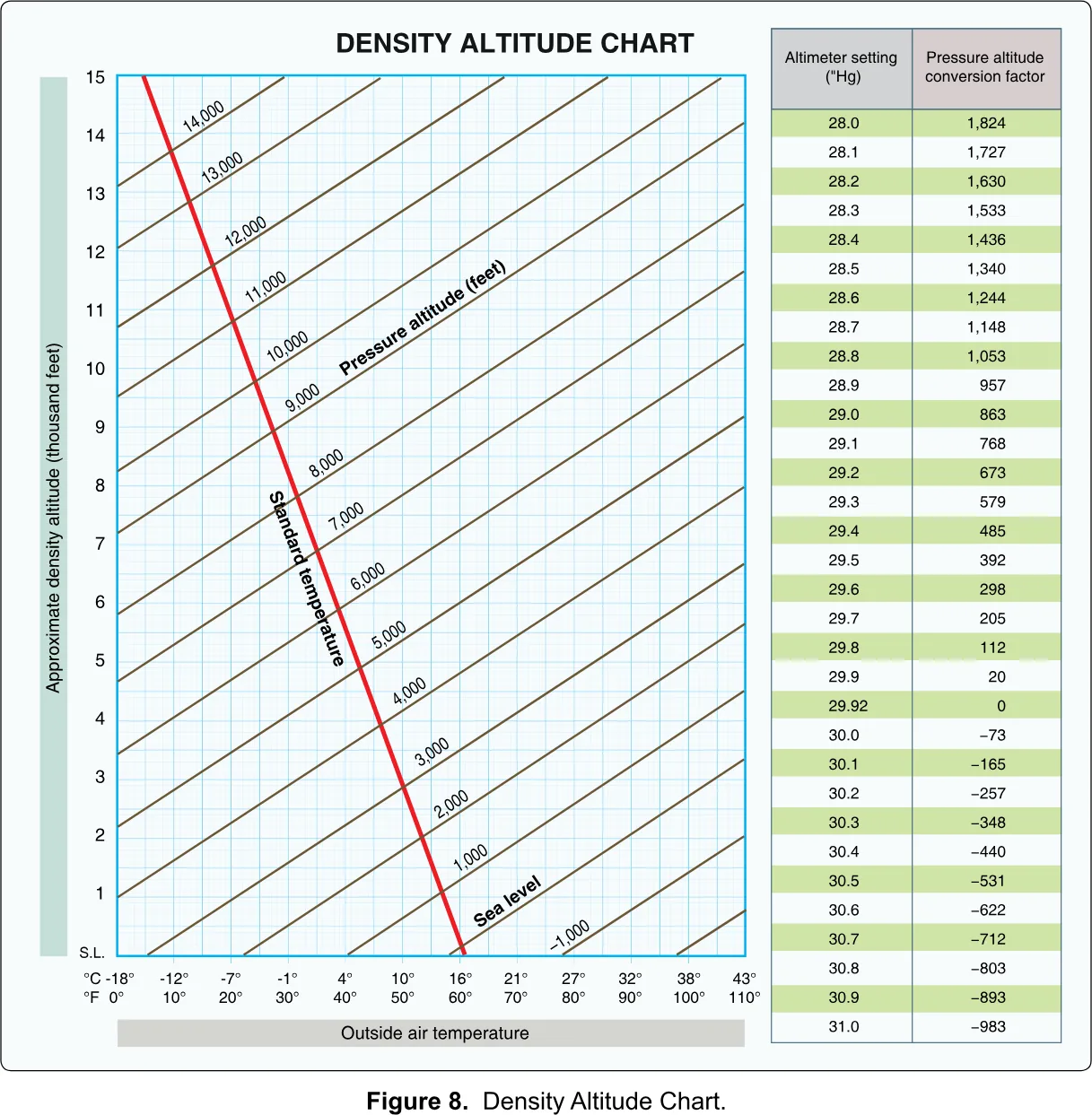
The method has three steps. First, get pressure altitude: add the conversion factor from the table to your field elevation. If the field is at 4,800 feet and the altimeter setting is 29.7, the table gives 205, so the pressure altitude is about 5,000. Second, find the outside air temperature along the bottom, say 90 degrees Fahrenheit. Third, climb the temperature line until it meets the slanted line for your pressure altitude, then read across to the side. You land at roughly 8,000 feet density altitude: a field at 4,800 feet that your aircraft treats as if it were 3,000 feet higher.
FAA-H-8083-25C, Ch. 11 · FAA-CT-8080-2H, Figure 8The red line on the chart marks standard temperature. If you are to the right of that line, the density altitude is higher than the pressure altitude; to the left, it is lower. That one visual check tells you whether the day is helping or hurting before you read any number.
The FAA sample questions treat density altitude as a concept: one asks what high density altitude does to propeller efficiency (it decreases it), and none asks you to read the chart. The chart is still in the supplement, so be able to use it. For the full interactive treatment, with sliders for pressure, temperature and humidity, see the lesson on density altitude.
§ 6.9 — THE MANNED-AIRCRAFT TABLES
The manned-aircraft weight and balance figures
The test supplement carries three figures that look like the weight and balance chapter of a pilot training book: Figure 32, Figure 33 and Figure 34. They are tables and graphs for a general-aviation airplane, with a pilot, passengers, fuel and baggage, expressed in pounds and thousands of inch-pounds.
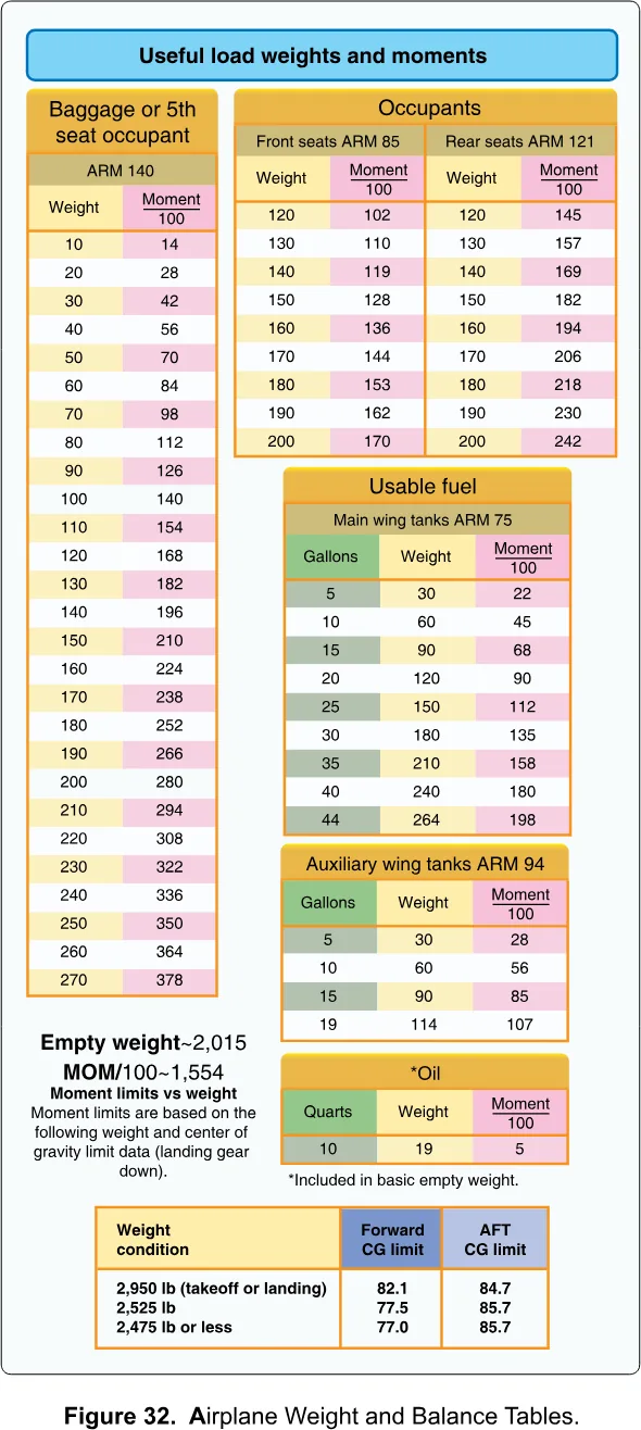
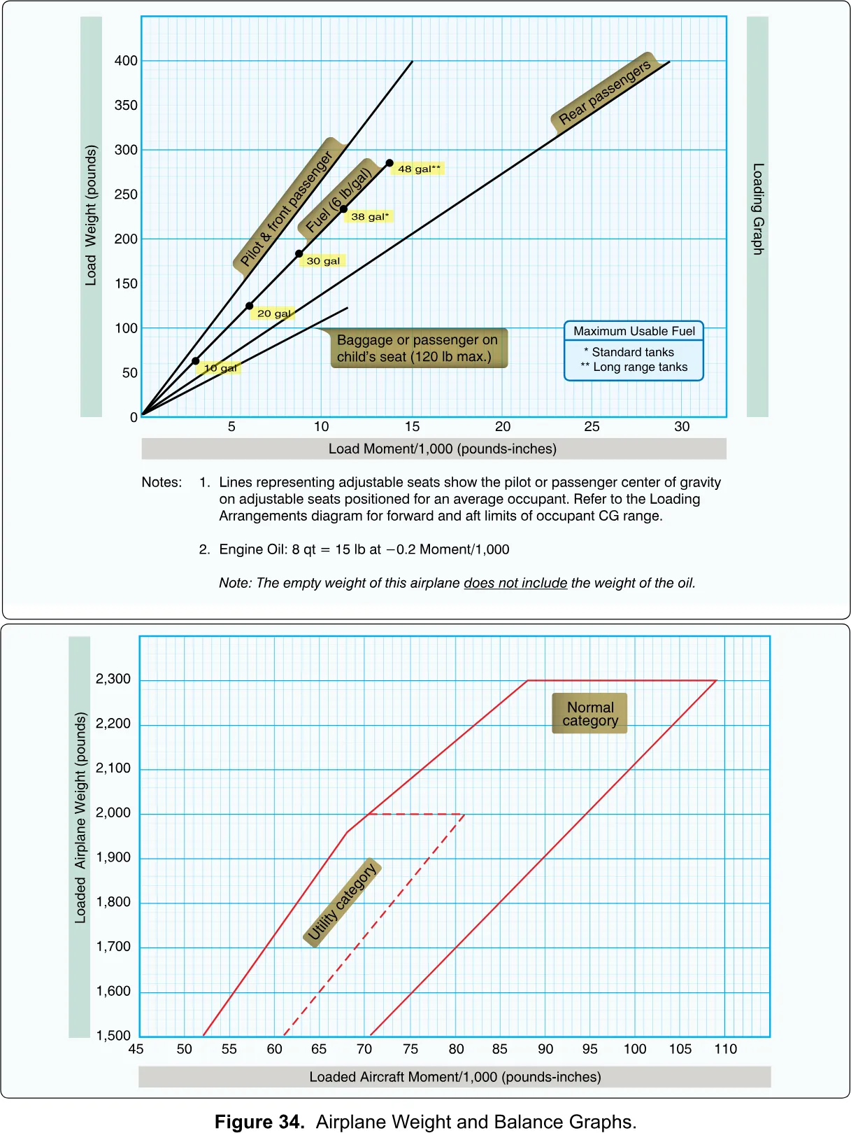
Figure 32 and Figure 33 give the weight-to-moment conversions; you look up the weight and read the moment. Figure 34 has two graphs. The upper one, the loading graph, lets you read a moment from a weight for each kind of load: pilot and front passenger, fuel, rear passengers and baggage. The lower one is the CG envelope: plot the aircraft’s total weight against its total moment, and if the point falls inside the outlined shape, the aircraft is within limits. Two shapes are drawn, labelled normal category and utility category.
FAA-CT-8080-2H, Figures 32 to 34The method is the same one in the worked example above: total weight, total moment, then CG. A table or graph is only a shortcut that does the multiplication for you.
These figures are in the supplement because the supplement is shared across several tests, including the manned-aircraft knowledge tests. The Part 107 general test draws on a smaller set. In the sample questions, the loading questions use Figure 2 and ask conceptual items about CG. None of the sample questions calls for Figures 32 to 34. Treat them as something to recognize and understand in principle, not something to drill.
§ 6.10 — BATTERIES AND POWER
Batteries, cold, and the preflight power check
Most of what you will fly is electric, so the battery is both your fuel tank and a performance limit. Two questions follow. Is there enough power for the whole flight? And does the battery deliver what it says on the label today?
The first is a regulation. Before flight, if the aircraft is powered, the remote pilot in command must ensure there is enough available power for the system to operate for the intended operating time.
14 CFR § 107.49(d)The phrase is intended operating time, not the manufacturer’s maximum flight time. If you plan a 20-minute mapping flight, a battery that is good for 25 minutes in a lab is a thin margin, and a battery at 60% is not enough. In practice that means checking battery level on both the aircraft and the control station before launching, which is also an item on the FAA’s sample preflight checklist, and planning a reserve for the flight home.
AC 107-2A, ¶ 7.3, item 23Cold is where the label stops being true. A lithium battery is a chemical device, and chemistry slows down in the cold. A cold battery cannot deliver current as freely, so its voltage sags under load, sometimes enough for the aircraft to report a low battery or even shut down in a hard maneuver, while the gauge says it is half full. It also holds less usable energy. A battery that gives 25 minutes in mild weather may give far fewer in freezing temperatures.
The FAA’s written material does not give cold-battery numbers, and it should not be treated as if it did. What it does give you is the pointer: manufacturers are encouraged to publish operating temperature limits, high and low, and the endurance and consumption levels appropriate to the power source. The AC also warns that lithium batteries can ignite when heated to extreme temperatures, damaged or improperly charged.
AC 107-2A, ¶ 8.12.2.5.1 · AC 107-2A, App. B.5The practical habits are ordinary ones. Keep batteries warm until just before flight. Hover a short while at low altitude and watch the voltage before committing to a long leg. Land early, not late. Treat swollen batteries and sudden drops in flight time as defects, not quirks: the FAA’s preflight table says a bulging battery casing may indicate impending failure resulting in abrupt power loss, and a diminishing flight time capability may indicate the same thing.
AC 107-2A, App. C, items 9 and 10§ 6.11 — WHO DECIDES
Whose job is it to know the performance?
By now the pattern is clear: nobody else is going to run these checks. The aircraft does not know whether it is overloaded. The manufacturer’s manual gives limits but does not look at your day. The regulation puts it on one person.
The remote pilot in command is directly responsible for, and is the final authority on, the operation of the small UAS. Before the flight that person has to assess the operating environment, including local weather, make sure the power is sufficient, and make sure that anything attached to the aircraft is secure and does not hurt its controllability.
14 CFR § 107.19(b) · 14 CFR § 107.49(a), (d), (e) FAA UAG sample questions, Q29 · 14 CFR § 107.19(b)This is what the ACS means by the importance and use of performance data. The objective is to be able to take the manufacturer’s numbers and adjust them for real conditions, and the adjustments are the ones in this chapter: today’s weight, today’s balance, today’s density altitude, today’s battery.
FAA-S-ACS-10B, UA.IV.A.K2If you are looking for a short procedure, it is this. Before each flight, ask four questions. What is on the aircraft, and does it match what the manufacturer allows? Is it secure, and is the balance right? How thin is the air today, and how warm or cold are the batteries? And given all of that, is the intended flight still within what the aircraft can do, with margin to spare? If any answer is uncertain, lighten the load, shorten the flight, or wait.
What to carry to the test
Four things are worth having cold. The formula: CG equals total moment divided by total weight. The bank table: 30 degrees gives 1.154, 45 gives 1.414, 60 gives 2.0, and you multiply the weight by the factor. The stall rule: a stall is a critical angle of attack problem, not a speed problem, and load factor raises stall speed. And the two ownership rules: follow the manufacturer’s loading instructions, and the remote pilot in command determines performance.
The deeper treatment of balance, with a beam you can slide weights along, is in the lesson on weight, balance and CG.
You should now be able to
- Calculate a CG as total moment divided by total weight, and say what happens when it moves out of limits
- Explain why an offset CG costs a multirotor control authority and flight time
- Read the load factor for a bank angle from Figure 2 and multiply it by the aircraft weight
- Say what a stall is and why a steep turn raises the stall speed
- Explain how weight, heat, humidity and altitude each reduce performance
- Read a density altitude from Figure 8
- State who is responsible for loading limits and performance, citing 14 CFR 107.49 and 107.19